
C A L I B R A T I O N OF CALIBRATORS PL-1239/USM-308(V),
P L - 1 2 3 9 A / U S M - 3 0 8 ( V ) (HP MODELS K04-8690A
AND 11531A)
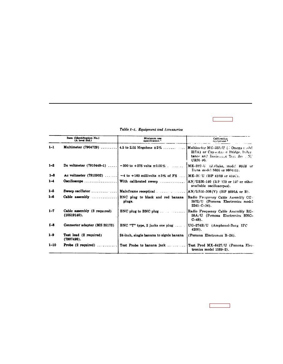
Equipment required for calibration performance checks and adjustments is listed in table 2-1.
1
Minimum use specifications are the principal paramerters required for performances of the calibration, and are included to assist in the selection
of alternate equipment.
Satisfactory performance of alternate items shall be verified prior to use.
All applicable equipment must bear evidence
current calibration.
1
The instruments utilized in this procedure were selected from those known to ve availiable in Department of Defense Installations, and the listing
by make or model number carries no implication of preference, recommendation, or approval by the Department of Defense for use by other agen-
cy. It is recognized that equivalent equipment produced by other manufacturers may be capable of equally satisfactory performance in the pro-
cedure.
NOTE
(1) Connect multimeter (1-1) to UUT DC-
VM connector with cable assembly (1-6).
Do not install UUT into sweep oscillator
(2) Set UUT FUNCTION SELECTOR
or RF unit holder.
switch to settings listed in table 2-2. Multimeter
indicates within specified limits.
2-2 Resistance
(3) Connect multimeter to UUT SCOPE
ACVM connector with cable assembly.
a. Performance Check.
11

