
Section II. CALIBRATION
5. Equipment Required
Equipment required for calibration performance checks and adjustments is listed in table 1.
NOTE
Minimum use specifications are the principal parameters required for performance of the
calibration and are included to assist in the selection of alternate equipment which may be used
at the discretion of the calibrating activity. Satisfactory performance of alternate items shall be
verified prior to use. All applicable equipment must bear evidence of current calibration.
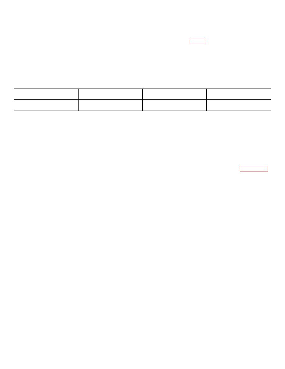
Table 1. Equipment Required
Minimum use
Calibration
Military
Item
specification if
equipment
equivalent
Dc voltmeter--------------------
24 Volts dc,
John Fluke
ME-202/U
+ 1 percent.
model 803B.
1 The calibration equipment utilized in this procedure was selected from those known to be available at
Department of Defense facilities and the listing by make or model number carries no implication of preference,
recommendation, or approval by the Department of Defense for use by other agencies. It is recognized that equivalent
equipment produced by other manufacturers may be capable of equally satisfactory performance in the procedure.
NOTE
It is recommended that personnel familiarize themselves with the entire procedure before
performing calibration.
6. Preliminary Procedure
This section includes instructions to prepare the unit under test for the calibration procedures outlined in paragraph 7.
This preliminary operating procedure places the power supply (PS1) in the unit under test in a turned-on condition. Verify
the results of the following turn-on and take corrective action if the requirements are not met, before proceeding.
a. Remove screws securing main assembly to protective case.
b. Carefully remove main assembly from protective case and place on workbench up side down to expose terminal
board TB2 and circuit card.
c. Operate CW/CCW switch to OFF and BLOWER switch to off (down) position.
d. Set ADJUST CURRENT and SERVO ADJUST controls fully counterclockwise.
e. Operate POWER switch to ON. Observe that POWER indicator illuminates.
NOTE
The following paragraph is divided into subparagraph a, Performance Check, and subparagraph
b, Adjustments.
When the performance check is within tolerance do not perform the
corresponding adjustment. When the performance check is not within tolerance, perform the
corresponding adjustment before continuing with the calibration procedure.
When the
performance check is not within tolerance and the adjustment cannot bring it into tolerance, the
deficiency must be corrected before continuing with the procedure.
7. Power Supply PSI Calibration
a. Performance Check.
(1) Connect dc voltmeter to test points TB2-1 (+) and TB2-3 (-) on unit under test.
(2) Observe that dc voltmeter indicates between 23.5 and 24.5 volts dc.
b. Adjustments. Rotate voltage adjust potentiometer on power supply circuit card to obtain 24-volts dc indication on
dc voltmeter.
8. Final Procedure
a. Deenergize unit under test, disconnect dc voltmeter, and reinstall main assembly in protective case.
b. In accordance with TM 38-750, annotate and affix calibration DA Label 80 (U.S. Army Calibration System).
When the unit under test cannot be adjusted to within tolerance, annotate and affix DA Form 2417 (Unserviceable Test
Instrument or Limited Use Tag).
3

