
(2) Position the controls on the unit under test
first position listed in the appropriate table. Adjust Signal
as indicated in (a), (b), and Ac) below:
Generator AN/URM-64(*) output power to maximum,
(a) OUTPUT control (TS-172/UP only)
internal modulation for 1,000-cps rate, and the output
to 8.
frequency for maximum (peak) indication on Indicator,
(b) INPUT control (TS-172/UP only) to
Standing Wave Ratio AN/ UPM-108A. Adjust Frequency
IN.
Comparator CM- 77(*)/USM and Frequency Converter
(c) READ RINGTIME-TUNE lever (TS-
CV-394/USA-5 as indicated in table 2. Frequency Meter
172A/UP only) to TUNE.
AN/USM-26(*) indication shall be within the limits
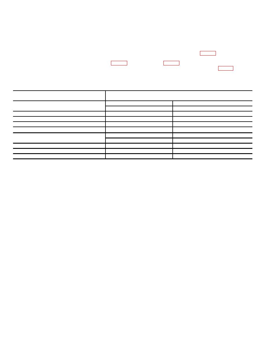
(3) Use A (for the TS-172/UP) or B, table 2
specified in table 2. Repeat the procedure for each unit
(for the TS-172A/UP) to adjust the unit under test to the
Table 2. Frequency Accuracy
A. TS-172/UP
Unit Under Test
Frequency Meter Indication
Frequency Dial Setting
(Frequency Counter) (MHz)
Min
Max
0
1210
1220
50
1260
1270
100
1310
1320
145
1355
1365
b. TS-172A/UP
Min
Max
1215
(1223)
*
1220
1226
1265
(1265)
*
1262
1268
1315
(1308)
*
1305
1311
1350
(1359)
*
1356
1362
* Frequencies listed in parentheses are typical of those obtained after correction factor has been applied to frequency dial
settings of 1215,1265, 1315, and 1350 MHz. Actual frequencies obtained may differ slightly; if so, perform the procedures
given in (4) through (9) below.
(4) Turn the unit under test frequency dial to
b. Adjustments.
1215 mc as indicated by numerical setting under left
(1) Remove the unit under test from the
index marker of the frequency dial.
protective case.
(5) Determine the actual frequency as the unit
(2) Repeat the procedure given in a(3) above
under test front panel marking instructs:
ACTUAL
with the unit under test frequency adjusted to 1315 mc.
FREQUENCY EQUALS DIAL READING PLUS OR
(3) Mechanically reset the unit under test
MINUS INDICATED CORRECTION.
(Correction is
frequency dial as indicated in (a) and (b) below.
indicated at the right index mark of the dial on the unit
(a) On the TS-172/UP only, reset the
under test.)
frequency dial to 100.
(6) Adjust the frequency comparator for zero
(b) On the TS-172A/UP only, remove
beat occurring nearest to one-tenth value of the actual
the locknut on the front of the frequency dial assembly;
frequency of the unit under test.
use the adjustment wrench provided with the unit under
(7) Adjust the frequency converter MIXER
test. Loosen the hold nut on the frequency dial and
control for the value nearest that obtained in (6) above.
adjust the frequency of the unit under test. Tighten the
(8) The indication on the frequency meter will
hold nut and then replace the locknut.
be within 300 kc of difference between the values
9. Meter Accuracy. a. Performance Check .
obtained in (6) and (7) above. For example, the actual
(1) Disconnect all test equipment and leads to
frequency for the dial setting of 1215 mc is equivalent to
the meter of the unit under test.
1219.0 mc.
The correct setting for the frequency
(2) Connect Meter Test Set TS-682/GSM1 to
comparator is 121.9 mc and the frequency converter
the meter terminals of the unit under test.
correct setting is 120 mc. The frequency meter should
(3) Adjust the meter test set for a 100
indicate 1.9 mc 300 kc, or 1.6 to 2.2 mc.
microampere reading on the unit under test meter.
(9) Repeat the procedures given in (4)
(4) The meter test set should indicate
through (8) above at the frequency dial settings of 1265,
between 98 and 102 microamperes.
1315, and 1350 mc.
5

