
TB 9-4920-454-35
(7) Repeat a (l) and a (3) through (8) above, as necessary, to ensure TEMP oC
indicator is in tolerance at both points.
NOTE
Perform paragraph 9 below only if adjustments were made in 8 b
above.
9. Calibrator Board
a. Performance Check
(1) Place thermometer adjacent to calibrator OUTPUT terminals. Wait 10 minutes
for thermometer to stabilize and record ambient temperature.
NOTE
Throughout this procedure it will be necessary to frequently
check the ambient temperature to assure proper millivolt
values in table 3 are applied.
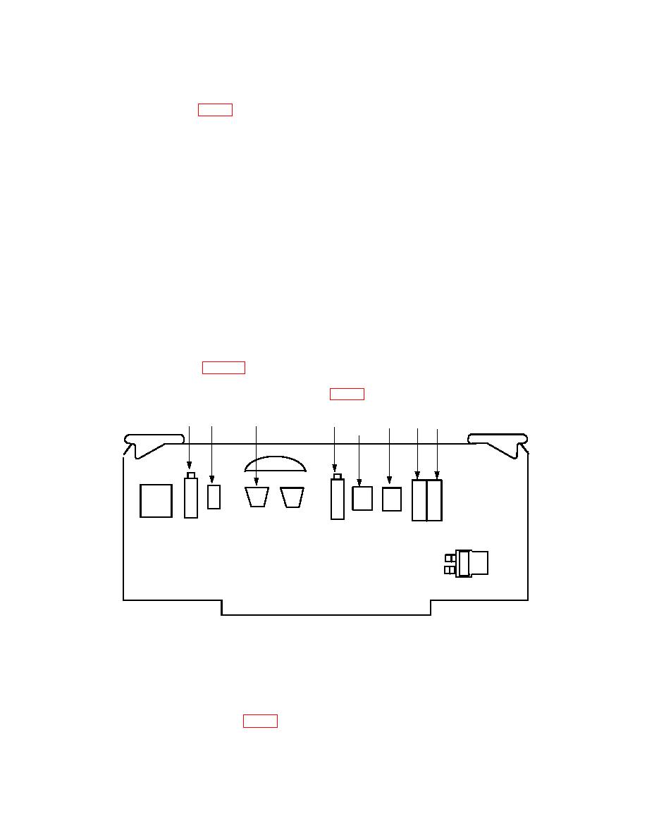
(2) Remove jumper from test point TP2 (fig. 4) on calibrator circuit board.
R6
TP4
TP2
R3
SIG
TP3
R8
R10
GND
(3) Disconnect Jl4 from Pl4 (located on left side of circuit board cage).
(4) Connect calibrator OUTPUT positive to the negative connectors of J14 and
TP4 on calibrator circuit board (fig. 4).

