
TB 9-4920-464-24
c. Unless otherwise specified, verify the result of each test and, whenever the test
requirement is not met, take corrective action before continuing with the calibration
adjustments required to calibrate the TI are included in this procedure. Additional
maintenance information is contained in the manufacturers' manuals for this TI.
d. Unless otherwise specified, all control and control settings refer to the TI.
7. Equipment Setup
HIGH VOLTAGE is used or exposed during the performance of
this calibration.
DEATH ON CONTACT may result if
personnel fail to observe safety precautions.
REDUCE
OUTPUT(S) to minimum after each step within the
performance check where applicable.
a. Remove TI front panel from its transit case by removing the 10 perimeter screws.
b. Apply input power to TI by performing the following:
(1) Ensure TI POWER switch is in the OFF position.
(2) Turn FUNCTION SELECTOR switch to AIRCRAFT SYSTEM TEST position.
(3) Connect TI power cable LTCT29329-01 P4 to connector J4 28VDC POWER INPUT.
(4) Connect power supply (+) to the small blade and (-) to the large blade of P2 of
LTCT29329-01.
(5) Supply 28 0.5 V DC to TI. Ensure a short is connected between negative
terminal and ground of power supply.
8. FLTS AC Voltmeter
a. Performance Check
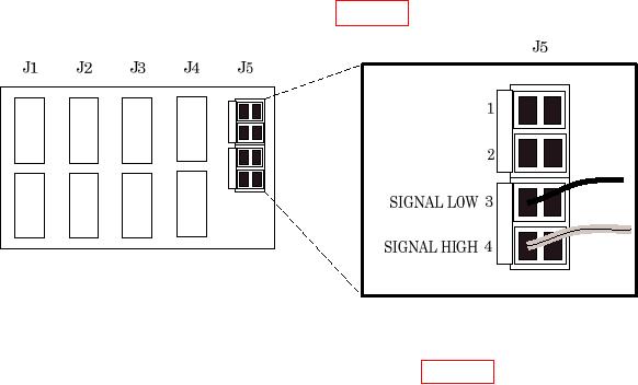
(1) Remove wires from pins 3 (SIGNAL LOW) and 4 (SIGNAL HIGH) of connector
J5 on rear of TI AC VOLTMETER as shown in figure 1 below.
Figure 1. AC voltmeter rear.
(2) Connect calibrator to pins 3 (SIGNAL LOW) and 4 (SIGNAL HIGH) of
connector J5 on rear of TI AC VOLTMETER as shown in figure 1 above.

