
TB 9-4931-495-24
(h) RF BLANKING switch (rear panel) to OFF.
(i) ALC switch to INT.
(j) RF switch to ON.
(k) FM-NORM-PL switch (rear panel) to NORM.
(3) Adjust POWER LEVEL control cw for maximum level power out.
(4) Press CW pushbutton and adjust CW MARKER pointer from high to low end of
frequency scale several times, then set CW MARKER pointer to 0.10 GHz. If microwave
frequency counter does not indicate within limits specified in table 12, perform the
appropriate adjustment listed in table 12.
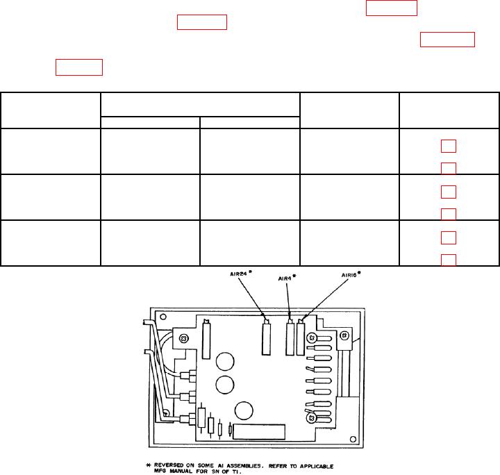
(5) Repeat technique (4) above at frequency settings listed in table 12. If
microwave frequency counter does not indicate within limits specified, perform adjustments
shown in table 12.
Table 12. Frequency Range (Models 8621A and B)
Test instrument
Microwave frequency counter
Test instrument
frequency dial
indications (GHz)
Figures
adjustments
settings (GHz)
Min
Max
BAND 1
0.10
0.080
0.120
A1R24 (R)
1.0
0.980
1.020
Compromise
2.0
1.980
2.020
A1R16 (R)
BAND 2
1.8
1.780
1.820
A2R10 (R)
3.0
2.980
3.020
Compromise
4.2
4.180
4.220
A2R9 (R)
BAND 3
3.2
3.170
3.230
A2R3 (R)
5.0
4.970
5.030
Compromise
6.5
6.470
6.530
A2R8 (R)
Figure 10. Model 86320A - adjustments.
28

