
TB 9-4935-558-50-1
transfer calibration standards set and are to be used in this calibration procedure. When
necessary, these items may be substituted by equivalent items unless specifically
prohibited.
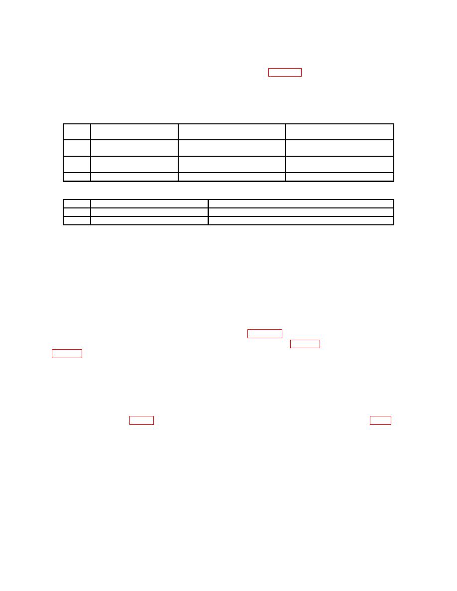
Table 2. Minimum Specifications of Equipment Required
Minimum use
Manufacturer and model
Item
Common name
specifications
(part number)
A1
SK-D--4850-107
2.1515 .001 in.
P/O SK-A-4850-103
A2
Weight set
8598963
94 1 lb.
P/O 10-10525
A3
Weight table
SK-A-4850-104
1 .25 lb.
Table 3. Accessories Required
Item
Common name
Description (part number)
B1
Calibration stand
SK-D-4850-106
B2
C-clamp
SK-D-4850-105
SECTION III
PRELIMINARY OPERATIONS
6. Preliminary Instructions.
a. The instructions outlined in this section are preparatory to the calibration process.
Personnel should become familiar with the entire bulletin before beginning the calibration.
b. Items of equipment used in this procedure are referenced within the text by common
name and item identification number as listed in tables 2 and 3. For the identification of
equipment referenced by item numbers prefixed with A, see table 2, and for prefix B, see
7. Equipment Setup.
a. Release any applied load on slide of TI force gage.
b. Stand the TI in an upright position on the calibration stand (B1). Tighten the
removed and the pointer on the gage just begins to deflect. Loosen adjusting screw slider
until all the load on the force gage is removed. Tap the slider with finger. The pointer of
the force gage should move with each finger tap if all the load is removed.
3

