
TB 9-6625-160-24
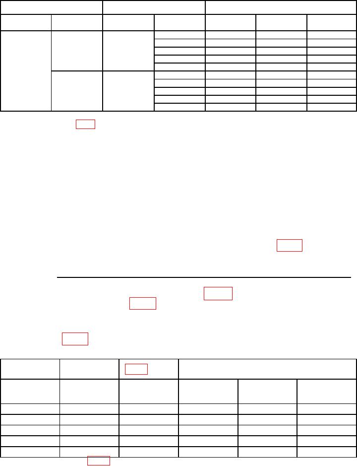
Table 8. AC Level Accuracy and Flatness (LOW INPUT) Continued.
TI
Calibrator
TI Limits Ratio (%)
Special
Ratio1
Level (V rms)
Min
Indicated (%)
Max
Function
(Hz)
1.19
0.07
0.07
20
98
102
1k
98
102
20 k
98
102
50 k
96
104
100 k
96
104
100 k2
0.007
0.007
96
104
50 k2
96
104
20 k2
98
102
1 k2
98
102
202
98
102
1 Key
in the Ratio numeric value only. DO NOT press the V or mV key.
2
Record values for use in table 9 below.
(14) Set CALIBRATOR to STBY.
(15) Connect CALIBRATOR to TI INPUT LOW connector through a 50 Ω
feedthrough termination. (Leave TI INPUT HIGH connector shorted to ground)
(16) Set TI RATIO to off (Led off).
(17) Set CALIBRATOR for -34 dBm at 20 Hz. Adjust CALIBRATOR output for a 7 mV
(as close as possible) indication on TI.
(18) Set TI RATIO button to on (Led on).
(19) Using CALIBRATOR controls, decrease signal of CALIBRATOR by 26 dB.
(34dBm 26dBm = 60dBm)
(20) Record % reading on TI right display in Indicated column of table 9 below.
% Recorded in step
above Equ.ivalent V Hz % recorded in step
above
C/R =
(21) Calculate computed ratio (C/R) using following formula:
%
(22) Record C/R in appropriate column of table 9 above. C/R must be within
corresponding limits specified in table 9 above.
(23) Set CALIBRATOR output to STBY.
(24) Repeat technique of (16) through (23) above for remaining parameters and
limits listed in table 9 above.
Table 9. AC Level Accuracy and Flatness (0.0007 V LOW INPUT).
Right display
TI computed ratio (C/R) (%)1
Calibrator
Table 8 reading
reading
Indicated
Calculated (C/R)
Frequency (Hz)
(%)
Indicated (%)
Min
(%)
Max
step (20)
step (22)
20
96
104
1k
96
104
20 k
96
104
50 k
96
104
100 k
96
104
These values will be used in table 11 below.
1
15

