
TB 9-6625-1963-24
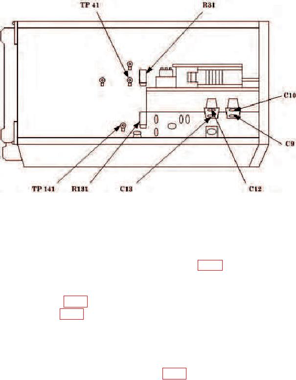
Figure 2. Left side view - component locations.
division vertical deflection on test oscilloscope.
(6) If oscilloscope does not display square wave with sharp leading corners, perform
b (1) below.
(7) Connect oscilloscope probe to test point TP41 (fig. 2). If oscilloscope does not
display square wave with sharp leading corners, perform b (2) below.
b. Adjustments
(1) Adjust R131 (fig. 2) for best leading corner of square wave (R).
(2) Adjust R31 (fig. 2) for best leading corner of square wave (R).
10. Input Compensation
a. Performance Check
(1) Connect function generator to TI A input using a 50
feedthrough termination.
(2) Connect oscilloscope to test point TP41 (fig. 2), using a X10 probe.
(3) Set A P-P SENS switch to 1V.
(4) Adjust function generator amplitude to obtain a 4 division vertical deflection on
oscilloscope. If roll off or spikes on square wave exceed 0.32 major division,
perform b (1) below.
(5) Set A P-P SENS switch to 10 V and repeat technique of (4) above. If roll off or
spikes on square wave exceed 0.32 major division, perform b (2) below.

