
TB 9-6625-2024-24
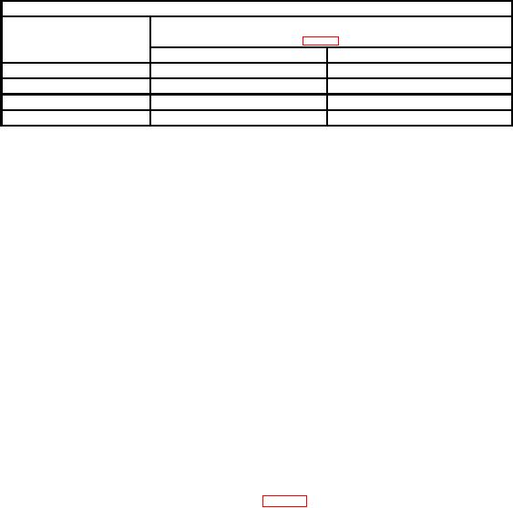
Table 6. Attenuator Compensation Adjustments
Test instrument
VOLTS/DIV
Adjustments
switch
(fig. 3) (R)
settings
Square corner
Flattop
10
mV
C106
C107
20
mV
C110
C111
50
mV
C114
C115
1
0.5 V
C118
C119
1Adjust
for square wave on + (positive) portion of square wave only.
b. Adjustments. No further adjustments can be made.
18. Risetime
a. Performance Check
(1) Set VOLTS/DIV switch to 50 mV.
(2) Connect oscilloscope calibrator SOURCE/MEASURE CHAN 1 to TI INPUT.
(3) Set oscilloscope calibrator EDGE output to 1 Ps and rotate oscilloscope
calibrator knob located below EDIT FIELD pushbutton for a convenient display on
oscilloscope.
(4) Adjust dual time base controls as listed in (a) through (c) below:
(a) TIME/DIV OR DLY TIME switches to .05 Ps.
(b) MAG X10 pushbutton to OUT.
(c) POSITION control for convenient display of pulse.
(5) Measure risetime using standard risetime technique. If risetime is not 5.4 ns
or less, perform b below.
b. Adjustments. Adjust C341 and R341 (fig. 3) for optimum square wave (R).
19. Final Procedure
a. Deenergize and disconnect all equipment.
b. Annotate and affix DA label/form in accordance with TB 750-25.
CALIBRATION PROCESS FOR DUAL TIME BASE TD-1085/U AND TD-1159/U,
AND TEKTRONIX TYPES 7B53A AND 7B53AN OPT 5 AND OPT 11S
20. Equipment Setup
a. Remove side panels from TI and install TI into oscilloscope horizontal (right)
compartment.
b. Press oscilloscope VERT MODE LEFT and TRIG SOURCE LEFT pushbuttons.
c. Position controls as listed in (1) through (8) below:

