
TB 9-6625-2071-24
(5) Disconnect function generator from TI.
(6) Connect signal generator RF OUTPUT to TI INPUT B using 50 Ω feedthrough
termination (omit termination for option H60).
(7) Set TI FREQ RESOLUTION, N switch to 10Hz, 105.
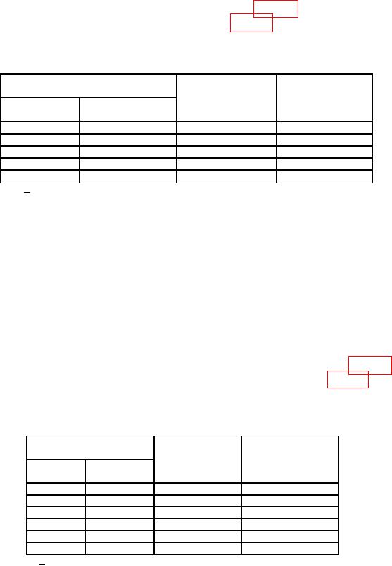
(8) Set signal generator for outputs listed in table 7. Slowly increase signal
generator amplitude until TI indicates as listed in table 7. If adjusted signal generator
amplitude exceeds limits specified, perform b (1) through (4) below (b (5) through (11)
below for AN/USM-459 and 5328AF096).
Table 7. Channel B Sensitivity.
Signal generator
Adjusted signal
output
Test instrument
generator output
Amplitude
indications
(mV)
(MHz)
(mV)
≤ 251
10
1.0
1.00000
≤ 251
30
1.0
3.00000
≤ 50
60
1.0
6.00000
≤ 50
90
1.0
9.00000
≤ 50
100
1.0
10.00000
<15 mV for AN/USM-459 and 5328AF096.
1
(9) Disconnect signal generator from TI.
(10) Set TI FREQ RESOLUTION, N switch to 1Hz, 106 and CHANNEL B DC/AC
switch to AC.
(11) Connect function generator Function Outputs Unbalanced to TI INPUT B using
50 Ω feedthrough termination (omit termination for option H60).
NOTE
In (12) through (16) below the TI indications are not critical but
should be stable. Only the channel B input sensitivity is being
checked.
(12) Set function generator for each sine wave output listed in table 8. Slowly
increase function generator amplitude until TI indicates as listed in table 8. If adjusted
function generator amplitude exceeds limits specified, perform b (1) through (4) below (b (5)
through (11) below for AN/USM-459 and 5328AF096).
Table 8. Channel B Sensitivity.
Function generator
Adjusted function
output (50 Ω)
Test instrument
generator output
indication
Amplitude
(mVp-p)
(kHz)
(mVp-p)
≤ 711
10.0
1.0
0.001000
≤ 711
0.020
1.0
0.000002
≤ 711
0.100
1.0
0.000010
≤ 711
1.0
1.0
0.000100
≤ 711
100.0
1.0
0.010000
≤ 711
1000.0
1.0
0.100000
<42 mVp-p for AN/USM-459 and 5328AF096.
1
9

