
TB 9-6625-2124-35
NOTE
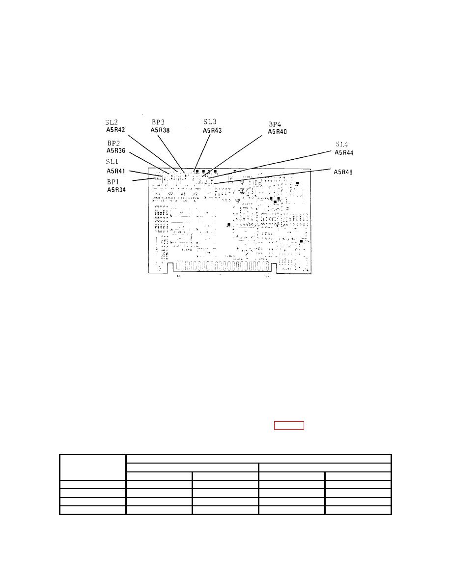
The BP adjustment determines at what frequency the
corresponding SL adjustment takes effect.
a. Performance Check
(1) Connect measuring receiver to RF OUTPUT.
(2) Press function keys and enter corresponding data on keyboard as listed in (a)
and (b) below:
(a) CW key, DATA ENTRY 12 GHz.
(b) POWER LEVEL key, DATA ENTRY 0 dBm.
(3) Press RF ON/OFF key to ON and establish a reference on measuring receiver
at 12 GHz.
(4) Make POWER LEVEL data entries as listed in table 9. Using standard tuned
level measurement techniques, measured power will indicate within limits specified.
Test instrument
Receiver system indications (dB)
power level
12 GHz
18 GHz
data entries
Min
Max
Min
Max
-10
-9.4
-10.6
-9.3
-10.7
-20
-19.3
-20.7
-19.1
-20.9
-30
-29.1
-30.9
-28.8
-31.2
-40
-38.2
-41.8
-38.0
-42.0

