
TB 9-6625-2132-35
9. Comparison Voltage and Linearity
NOTE
For Type 7A13, SN B199999 and below, perform steps (1)
through (6) below. For Type 7A13, SN B200000 and above,
perform (7) through (9) below.
a. Performance Check
(1) Position TI controls as listed in (a) through (c) below:
(a) +INPUT pushbutton to GND.
(b) VOLTS/DIV switch to 1 mV.
(c) VOLTS counter to 9.999 plus 1 digit to indicate 9.000 (cw to 0.000 for TI
with electrical counter).
(2) Connect multimeter between TI Vc OUT 0-10V jack and chassis ground.
(3) Press polarity + (positive) pushbutton. If multimeter does not indicate between
+9.985 and +10.015 V dc, perform b (1) below. Press polarity - (negative) pushbutton. If
multimeter does not indicate between -9.985 and -10.015 V dc, perform b (1) below.
(4) Adjust VOLTS counter to indicate 0.999 plus one digit to indicate 0.000 (ccw to
1.000 for TI's with electrical counter). If multimeter does not indicate between -0.994
and -1.0006 V dc, perform b (2) below.
(5) Press polarity pushbutton to + and adjust VOLTS counter to 0.100. Multimeter
will indicate between +0.0944 and +0.1051 V dc.
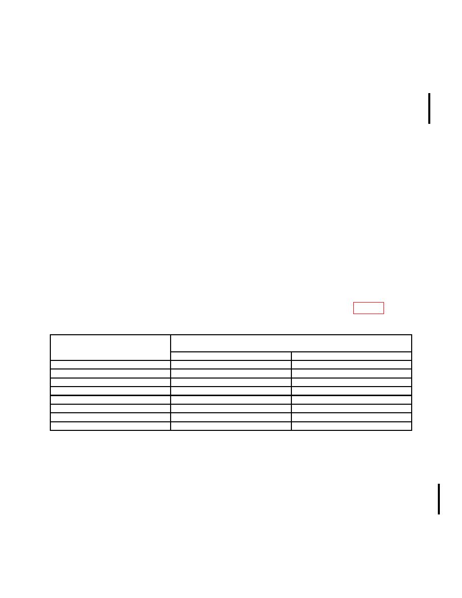
(6) Repeat technique of (5) above for VOLTS counter settings listed in table 4.
Multimeter will indicate within limits specified.
Multimeter indications
Test instrument
(V dc)
VOLTS counter settings
Min
Max
0.300
0.2947
0.3053
0.500
0.4945
0.5055
0.700
0.6943
0.7057
1.000
0.994
1.006
3.000
2.992
3.008
5.000
4.990
5.010
7.000
6.988
7.012
9.000
8.986
9.014
(7) Press polarity + (positive). Repeat technique of (1) and (2) above. If multimeter
does not indicate between +9.985 and +10.015 V dc, perform b (3) below.
(8) Press polarity - (negative) pushbutton. If multimeter does not indicate between -
9.985 and -10.015 V dc, perform b (4) below.
(9) Press polarity + (positive) pushbutton. Adjust COARSE and FINE controls
until VOLTS counter indicates 5.000. If multimeter does not indicate between +4.997 and
+5.003 V dc, perform b (5) below.
CHANGE 1

