
TB 9-6625-2155-35
7. Equipment Setup
HIGH VOLTAGE is used or exposed during the performance of
this calibration.
DEATH ON CONTACT may result if
personnel fail to observe safety precautions.
REDUCE
OUTPUT(S) to minimum after each step within the
performance check where applicable.
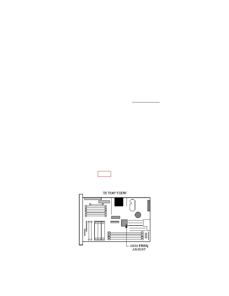
a. Remove TI from protective cover only as necessary to make adjustments. Replace
cover after completing the adjustments.
NOTE
For the remainder of this procedure the 68369NV connected to
the measuring receiver will be called the local oscillator.
NOTE
Many indications, such as MESSAGE, ∆F, SWEEP FREQ
START, etc., will only appear when the appropriate entry
pushbutton is pressed and held in the IN position.
b. Connect TI to a 115 V ac power source.
c. Set LINE switch to ON and allow a 2 hour warm-up and stabilization.
difference meter. Set FREQUENCY STANDARD INT/EXT SWITCH to INT.
frequency difference meter.
indication.

