
TB 9-6625-2162-24
Connection B
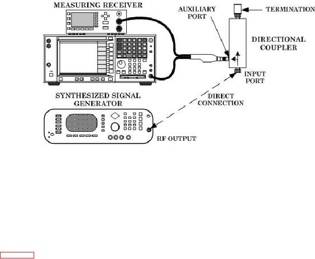
Figure 4. Directional coupler ratio check (connection B).
(2) Set synthesized signal generator for an output of 0 dBm at 8.4 GHz.
(3) Configure measuring receiver to measure power at 8.4 GHz. Vary synthesized
signal generator output level for a measuring receiver indication as close as possible to
0.0 dBm and establish a 0 dB reference.
(4) Set synthesized signal generator output off and connect equipment as shown in
figure 4, connection B.
(5) Set synthesized signal generator output on and measure and record power
measurement as shown on measuring receiver as output coupling ratio.
(6) Repeat steps (1) through (5) above at synthesized signal generator frequencies
from 8.4 to 10.0 GHz in 0.1 GHz increments.
NOTE
Output coupling values recorded in (5) above are to be used as
listed in (a) through (e) below:
EXAMPLE:
(a) Recorded output coupling value at 9.2 GHz is 9.3 dBm.
(b) A 9.3 dBm indication on measuring receiver would equal a 0.0 dBm
directional coupler output.
(c) A 1.3 dBm indication on measuring receiver would equal a (+) plus 8.0
dBm directional coupler output.
(d) A 11.3 dBm indication on measuring receiver would equal a () negative
2.0 dBm directional coupler output.
(e) A +0.7 dBm indication on the measuring receiver would equal a (+) plus 10.0
dBm directional coupler output.
14

