
TB 9-6625-2183-24
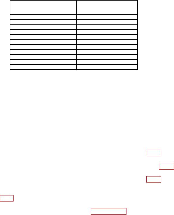
Table 6. Timing - Continued
Test instrument
Oscilloscope calibrator
MARKER
SEC/DIV switch
output
settings
0.2 m
0.2 ms
0.5 m
0.5 ms
1m
1 ms
2m
2 ms
5m
5 ms
10 m
10 ms
20 m
20 ms
50 m1
50 ms
0.1
0.1 s
0.2
0.2 s
0.5
0.5 s
1Release
AUTO/NORM pushbutton to NORM.
(9) Set switches as listed in (a) through (c) below:
(a) VOLTS/DIV to 5 m.
(b) SEC/DIV to X-Y.
(c) Display mode to CH2 (X-Y).
(10) Connect oscilloscope calibrator SOURCE/MEASURE CHAN 1 to CH1 X INPUT.
(11) Set oscilloscope calibrator for a 10 kHz, 20 mV, VOLTAGE mode output.
(12) Adjust oscilloscope calibrator rotary knob below EDIT FIELD button for 4
divisions between 2 dots displayed. If oscilloscope calibrator err readout indication is not
within 4%, perform b (4) below.
b. Adjustments
(1) Set oscilloscope calibrator MARKER output to 5 s and adjust C562 (fig. 1) for 1
marker per division (R).
(2) Set oscilloscope calibrator MARKER output to .5 s and adjust C612A (fig. 2)
for 1 marker per division (R).
(3) Set oscilloscope calibrator MARKER output to .1 s and adjust C635 (fig. 2) for 1
marker per division (R).
(4) Set oscilloscope calibrator for a 10 kHz, 20 mV, VOLTAGE mode output and
adjust R143 (fig. 1) for 4 divisions between the 2 dots displayed (R).
NOTE
If adjustments are performed, repeat paragraphs 13 and 14
until no further adjustments can be made.
15. Calibrator
a. Performance Check
(1) Connect .3 V CAL OUT jack to CH1 X INPUT.
(2) Set VERT MODE switch to CH1 and SEC/DIV switch to .2m.

