
TB 9-6625-2185-35
(10) Connect sensor to level generator 50Ω output.
(11) Press pushbuttons 0, RANGE HOLD, 39.80, MODE dB.
(12) Wait 30 seconds for settling and press pushbuttons 0, dB LIMITS HI, CAL,
REF LVL dB. Record display indication (approximately 5000) as range 0 gain.
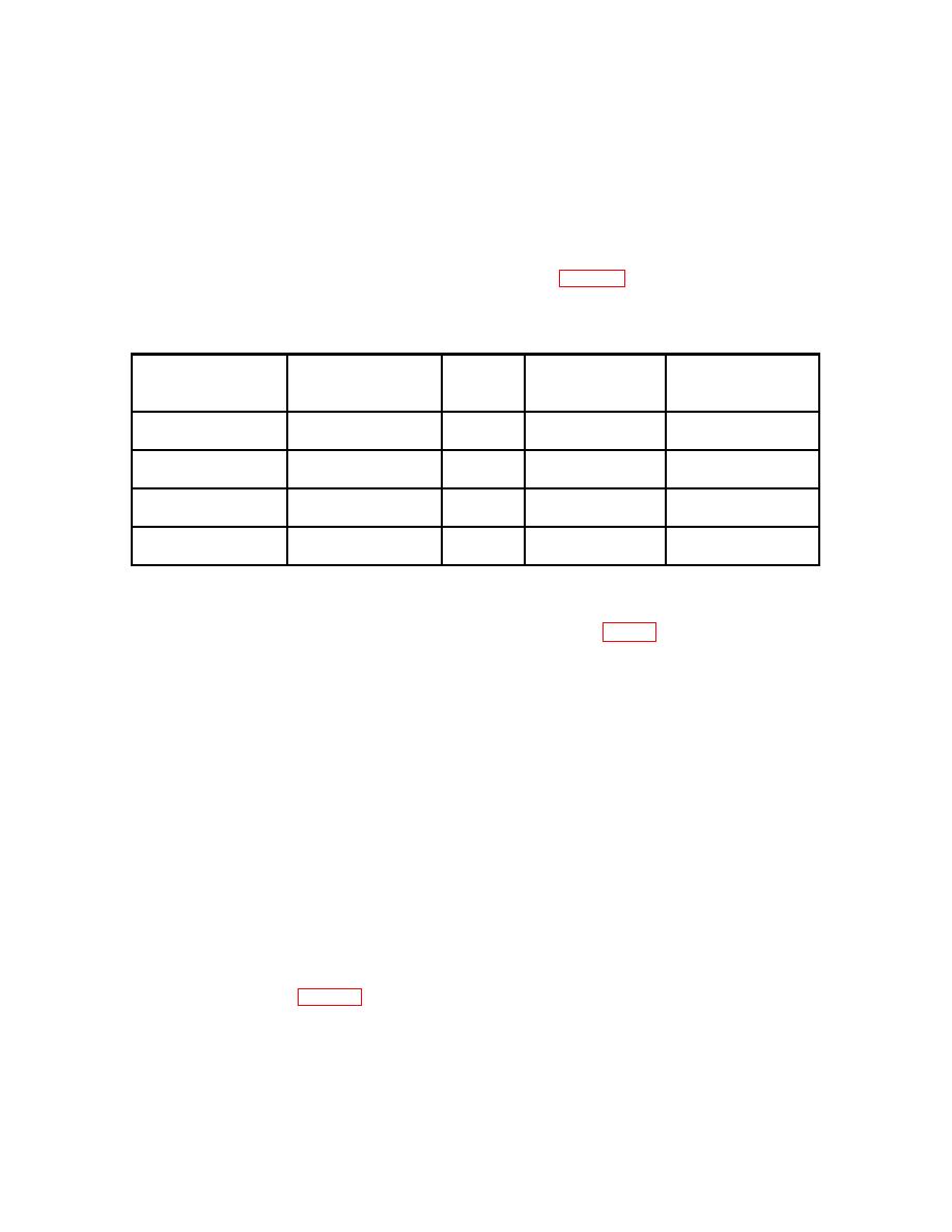
(13) Repeat technique of (9), (11), and (12) above for level generator output, TI
pushbuttons and record display indications as listed in table 4.
Level generator set to
50 MHz
Allow
Record
(dBm)
Press
settings
Press
display
-24
1, RANGE HOLD, 3,
---
0,dB LIMITS HI,
Range
1
=
9, ., 8, 0, MODE dB
CAL, REF LVL dB
approximately 5000
-14
2, RANGE HOLD, 3,
---
0,dB LIMITS HI,
Range
2
=
9, ., 8, 0, MODE dB
CAL, REF LVL dB
approximately 5000
-4
3, RANGE HOLD, 3,
---
0,dB LIMITS HI,
Range
3
=
9, ., 8, 0, MODE dB
CAL, REF LVL dB
approximately 5000
+6
4, RANGE HOLD, 3,
---
0,dB LIMITS HI,
Range
4
=
9, ., 8, 0, MODE dB
CAL, REF LVL dB
approximately 5000
(14) Set level generator to STANDBY, allow sensor to settle for 30 seconds.
(15) Set control board bit switch to OPERATE MODE (fig. 3).
(16) Press pushbuttons RANGE AUTO, MODE PWR, and ZERO (cc03 when
complete).
(17) Turn level generator to ON and position controls for 50 MHz, -30 dBm output.
Record display indication as range 1 downscale reading.
(18) Compute downscale sensor correction as follows: Subtract downscale reading
recorded in (17) above from 1.000 W.
NOTE
Disregard decimals, always use whole numbers when
computing downscale correction.
Example: 1.000 W minus downscale reading of 1.008 W
equals a downscale of -8.
(19) Record calculated value as range 1 down scale correction.
(20) Repeat technique of (17) through (19) for level generator settings and record
corrections as listed in table 5.
15

