
TB 9-6625-2211-24
(3) Set MEASUREMENT FUNCTION SEL switch to PRF
EXT
and
MEASUREMENT PRF RANGE switch to the first setting listed in table 5.
(4) Adjust pulse generator period controls to obtain the first MEASUREMENT
meter indication listed in table 5. Frequency counter will indicate within limits specified.
If not, perform b below.
(5) Repeat technique of (3) and (4) above for remaining MEASUREMENT PRF
RANGE switch settings and MEASUREMENT meter indications listed in table 5.
Frequency counter will indicate as specified. If not, perform b below.
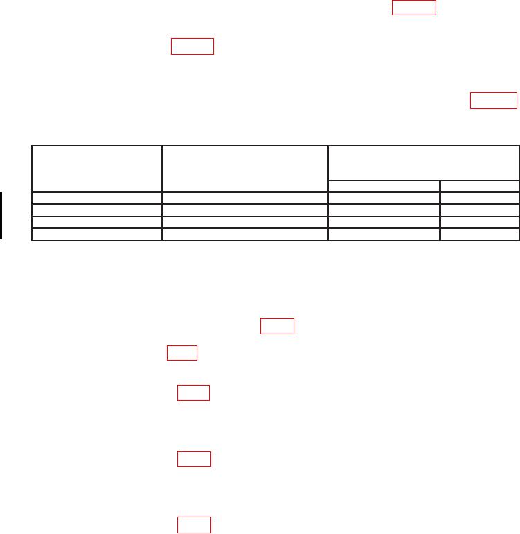
Table 5. Pulse Repetition Measurement
MEASUREMENT PRF
Frequency counter indications
MEASUREMENT
RANGE
(Hz)
switch settings
meter indication
Min
Max
X10
10
95
105
X1K
1
950
1050
X1K
2
1095
2050
X100
10
950
1050
b. Adjustments
(1) Set MEASUREMENT PRF RANGE switch to X1K.
(2) Connect oscilloscope to A10TP3 (fig. 1), using X10 probe.
(3) Adjust A10R27 (fig. 1) until (+) slope duration as indicated on oscilloscope is 99 Ps (R).
(4) Adjust pulse generator period controls for a 2.00 kHz frequency counter
indication. Adjust A10R16 (fig. 1) for a MEASUREMENT indication of 2 (R).
kHz. Set MEASUREMENT PRF RANGE switch to X100.
(6) Adjust A10R20 (fig. 1) for a MEASUREMENT meter indication of 10 (R).
Hz. Set MEASUREMENT PRF RANGE switch to X10.
(8) Adjust A10R24 (fig. 1) for a MEASUREMENT meter indication of 10 (R).
(9) Repeat (1) through (8) above until no further adjustment is required.
10 CHANGE 1

