
TB 9-6625-2211-24
(9) Connect equipment as shown in figure 2, connection B.
(10) Measure the delay time between the leading edges of the pulses on Channel 1
and Channel 2 of oscilloscope. The delay time will be <0.5 Ps.
(11) Measure the amplitude of the pulse on Channel 2 of oscilloscope. The amplitude
will be 5.0 1 V.
(12) Set pulse generator POLARITY switch to NEG. Repeat (2) through (11) above.
b. Adjustments. No adjustments can be made.
12. Range Delay Accuracy
a. Performance Check
(1) Position controls as listed in 7 d above.
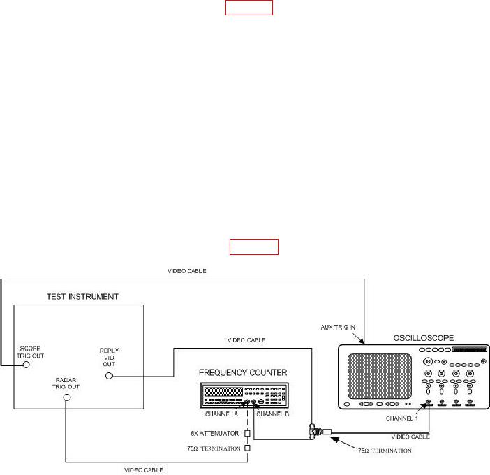
(2) Connect equipment as shown in figure 3.
Figure 3. Range delay - equipment setup.
(3) Set PRT SEL (USEC) (500 USEC MIN) switches to 9999.
(4) Adjust frequency counter controls to measure TIME INT. A to B. Frequency
counter will indicate 434.0 0.7 Ps.
(5) Set REPLIES MODULATION SEL switch to M4-3P. Frequency counter will
indicate 449.0 0.7 Ps.

