
TB 9-6625-2237-24
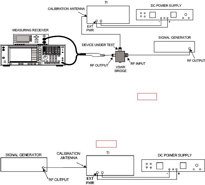
Figure 2. Minimum antenna power equipment setup.
(7) Set signal generator frequency controls for 243.0 MHz output and adjust
amplitude output controls to same value as recorded in table 4 for signal generator
amplitude output indication for test setting of 19.1 dBm.
(8) Set measuring receiver to measure frequency then power level.
(9) Adjust antenna load carriage assembly for a minimum indication on measuring
receiver FREQUENCY/LEVEL display (-9.2 dBm maximum).
(10) Press signal generator RF OFF/ON key to OFF position.
(11) Connect equipment as shown in figure 3.
Figure 3. Threshold point - equipment setup.
(12)
Adjust dc power supply controls for a multimeter indication between 12.5 and
13.5 V dc.
(13) Open antenna carriage assembly and carefully tighten load carriage assembly
locking knob. Record position of the carriage.
(14) Close antenna chamber assembly.
(15) Remove CALIBRATION ADJUSTMENT RF MODULE cover plate.
(16) Press signal generator RF OFF/ON key to ON position.
(17) Press and hold RF POWER PRESS button. The red FAIL and green PASS
indicators will blink randomly; if not, perform b (l) below for 243.0 MHz or b (2) below for
282.8 MHz.
8

