
TB 9-6625-2240-35
(6) Rotate oscilloscope calibrator knob below EDIT FIELD pushbutton to adjust for
6 divisions of vertical deflection on TI. Oscilloscope calibrator err display will indicate as
specified in table 21, if not perform b below.
Oscilloscope calibrator
Test instrument
VOLTAGE
Err
Test instrument
output settings
display limits
switch settings
VOLTS/DIV
TIME/DIV Amplitude
(%)
50 m
.2 ms
300 mV pp
1 kHz
1
b. Adjustments
(1) Set oscilloscope calibrator VOLTAGE output as listed in table 21.
(2) Adjust TI VOLTS/DIV controls for 6 divisions of vertical deflection on TI.
(3) Disconnect oscilloscope calibrator from TI and connect TI CALIBRATOR (front
panel) and (ground) (front panel) to TI CH1 input.
(4) Adjust R1515 (fig. 3) for 6 divisions of vertical deflection on TI (R).
13. Power Supply
NOTE
Do not perform power supply checks if all other parameters are
within tolerance.
a. Performance Check
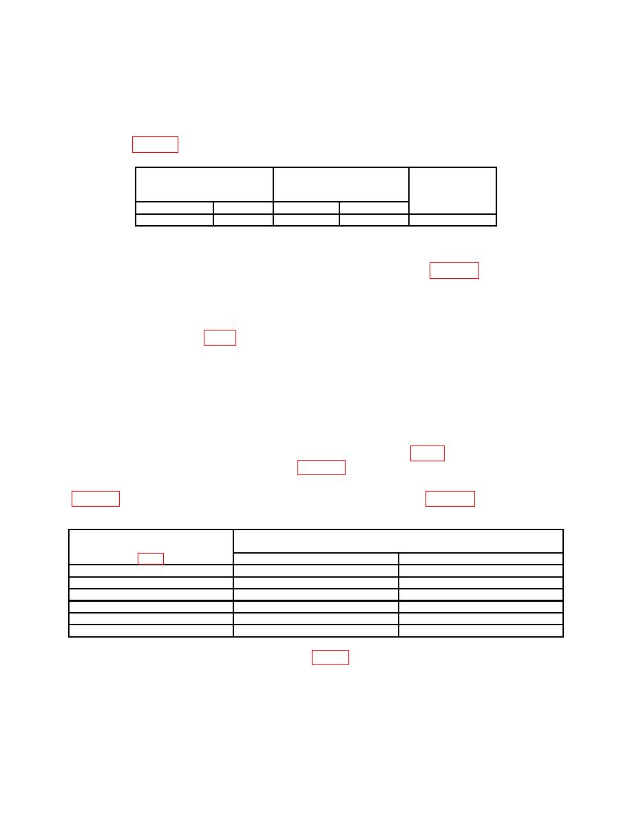
(1) Connect digital multimeter to TI test point +50 V (fig. 3) and chassis ground.
Digital multimeter will indicate as listed in table 22 below; if not, perform b below.
(2) Repeat technique of (1) above for TI test points and voltage indications listed in
Test instrument
Digital multimeter indications
test points
(V dc)
Min
Max
+50
V
+49.75
+50.25
+110
V
+107
+113
+15
V
+14.77
+15.23
+5
V
+4.92
+5.08
-15
V
-14.77
-15.23
-8
V
-7.88
-8.12
+50 V (R).

