
TB 9-6625-2240-35
(21) Rotate oscilloscope calibrator knob below EDIT FIELD pushbutton to adjust
amplitude for 5 divisions of vertical deflection on TI. Adjust standardizer for optimum
square wave presentation. If optimum square wave presentation cannot be obtained,
perform adjustments listed in table 17.
(22) Repeat technique of (21) above for remaining TI VOLTS/DIV switch settings
listed in table 17 (do not readjust standardizer). If optimum square wave presentation
cannot be obtained, perform adjustments listed in table 17
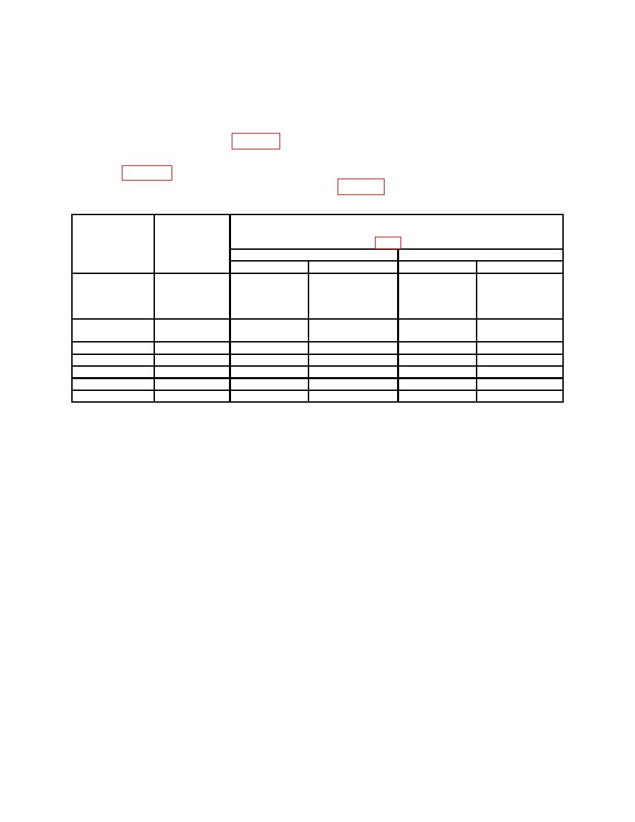
Test instrument
Oscilloscope
Test
CH1 and CH 2 adjustments
calibrator
instrument
(fig. 1) (R)
EDGE
VOLTS/DIV
Tektronix, Type 475
Tektronix, Type 475A
settings
settings
Square corner
Flat top
Square corner
Flat top
500
mV pp
5m
---
C10
---
---
(CH1)
1
C50
(CH2)
1
1
V pp
10
m
C36
C37
---
C10 (CH1)1
C50 (CH2)2
1
V pp
20
m2
C34
C35
C36
C37
250
mV pp
50
m3
C32
C33
C34
C35
500
mV pp
.1
---
---
C32
C33
1.25
V pp4
.5
C30
C31
---
---
1.25
V pp4,5
1
---
---
C30
C31
1 Adjust
for optimum results between square corners and flat tops.
2 Remove
termination from setup.
3 Attenuators from setup.
4 Maximum amplitude for oscilloscope calibrator. Make adjustments as best as possible.
5.Adjust A TRIGGER for a stable display if required.
(23) Connect oscilloscope calibrator CHAN 1 to TI CH1 through 50Ω feedthrough
termination.
NOTE
Ensure 50Ω feedthrough termination, wattage, and frequency
ratings are adequate for test below.
(24) Position controls as listed in (a) through (d) below:
(a)
TRIG MODE AUTO pushbutton pressed (in).
(b)
X10 MAG pushbutton pressed to on (in).
(c)
Press and release 20 MHz BW/TRIG VIEW pushbutton to full bandwidth.
(d)
VERT MODE CH1 pushbutton pressed (in).
NOTE
Ensure oscilloscope calibrator FASTEDG and TDPULSE are
off when performing steps below.
18

