
TB 9-6625-2283-24
(8) Set POWER switch to ON while pressing the SWEEP pushbutton on TI. TI
will enter calibration aid mode.
(9) Press READOUT MODE (LOSS) pushbutton.
(10) Adjust 0 dB SET control to set one of the displayed lines on the center graticule line.
(11) Adjust R1064 (fig. 2) until all displayed lines coincide with graticule lines (R).
(12) Press READOUT MODE (DIST) pushbutton.
(13) Adjust R1044 (fig. 2) to set one of the displayed lines on the center graticule line.
(14) Adjust R1048 (fig. 2) until all displayed lines coincide with graticule lines (R).
(15) Switch between readout mode loss measurement and readout mode distance
measurement functions by pressing READOUT MODE (LOSS, DIST) pushbutton and
adjust R1022 (fig. 2) for the straightest possible lines (R).
(16) Set DIST/DIV switch to 1 and press and hold SWEEP pushbutton until trace
returns on screen.
(17) Position the trace by adjusting the
POSITION control and set DIST/ DIV
switch to 1000.
(18) Press FILTER (FAST) pushbutton and VERTICAL SCALE 5 dB/DIV pushbutton.
POSITION control.
(19) Position the noise to midscreen by adjusting the
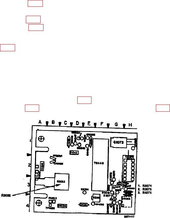
(20) Defocus one of the dots with R3033 (fig. 3) (R).
Figure 3. High voltage power supply circuit board.
(22) Press READOUT MODE (LOSS, DIST) pushbutton to READOUT MODE
LOSS position.
8

