
TB 9-6625-2293-35
(30) Push up and release TRIGGER COUPLING switch, and position calibration
generator controls for 1 S/D output.
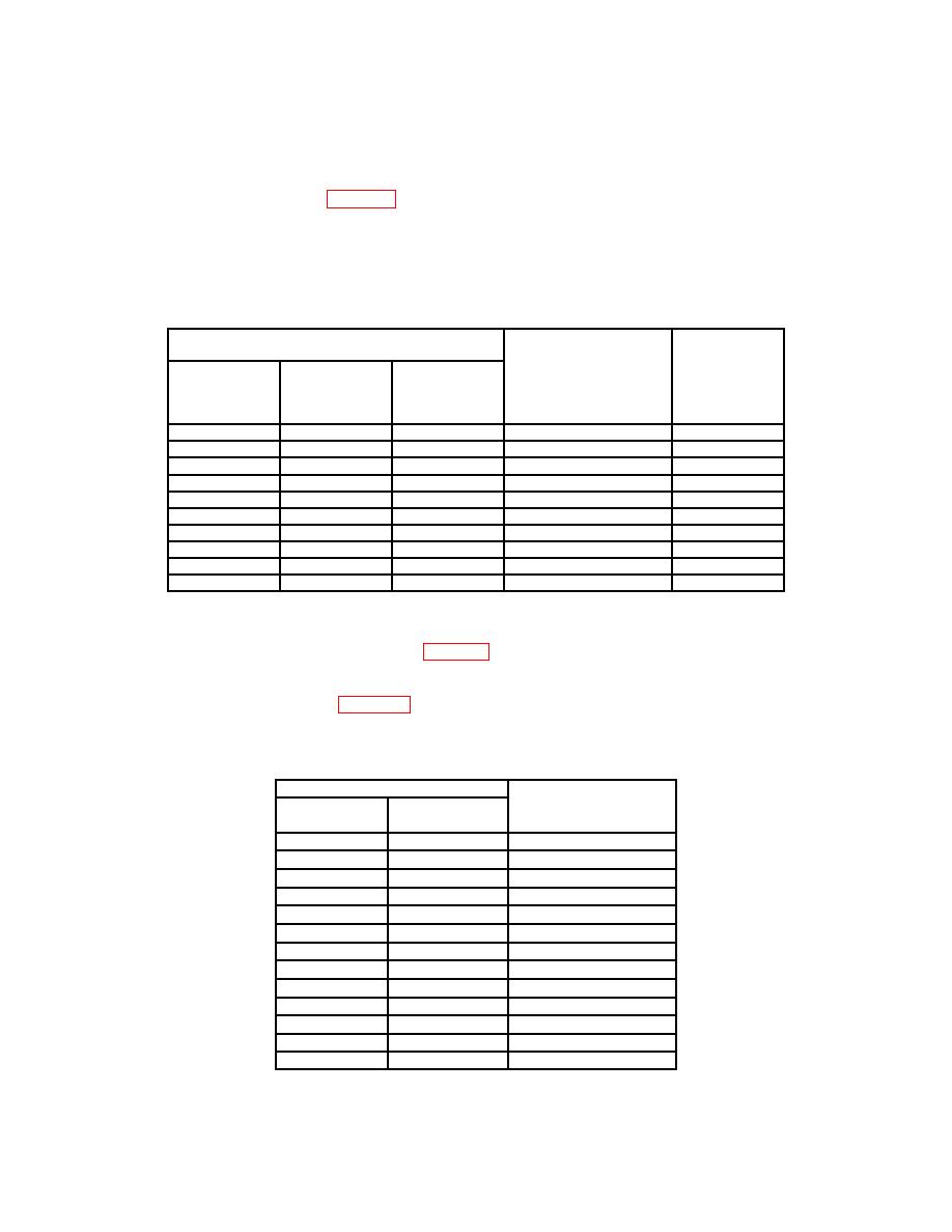
(31) For each step in table 13 do the following:
(a) Adjust ∆REF OR DLY POS and ∆ controls as necessary, to intensify
indicated time markers on the A sweep and superimpose displayed B sweep time markers
within listed limits.
(b) Push up and release TRIGGER COUPLING switch.
Test instrument
Test
instrument
superimposed
Display
Oscilloscope calibrator
displayed
∆REF
∆t
step
output
B sweep
division
number
time marker
marker
settings
S/D
7
2
10
1
0.2
S/D
8
2
10
2
0.2
S/D
91
4
28
2
1.2
S/D
10
2
10
10
0.2
S/D
11
2
10
50
0.2
S/D
121
4
28
50
1.2
S/D
13
2
10
.5
0.2
S/D
141
4
28
.5
1.2
S/D
15
22
10
.1
0.2
16
22
10
20
nS/D
0.1
1If
∆ control is adjusted at step 9, 12, or 14 the previous step will be repeated.
2Intensify
starts on indicated time marker and may cover more than 1 time marker.
(32) After completion of step 16 of table 13 TI display will indicate ADJ ∆, (step) 17, 1 s.
(33) Adjust TRACE SEP control fully cw.
(34) For each step in table 14 (except step 28) adjust ∆ control for listed number of
time markers over center 8 divisions then push up and release TRIGGER COUPLING
switch.
Test instrument
Displayed
Time markers
calibrator
Step
over 8 divisions
output settings
S/D
17
8
1
S/D
18
24
1
S/D
19
8
2
S/D
20
24
2
S/D
21
8
10
S/D
22
8
50
S/D
23
24
50
S/D
24
8
.5
S/D
25
24
.5
S/D
26
8
.1
27
8
20
nS/D
28
2
2
nS/D
29
8
1
mS/D
27

