
TB 9-6625-2293-35
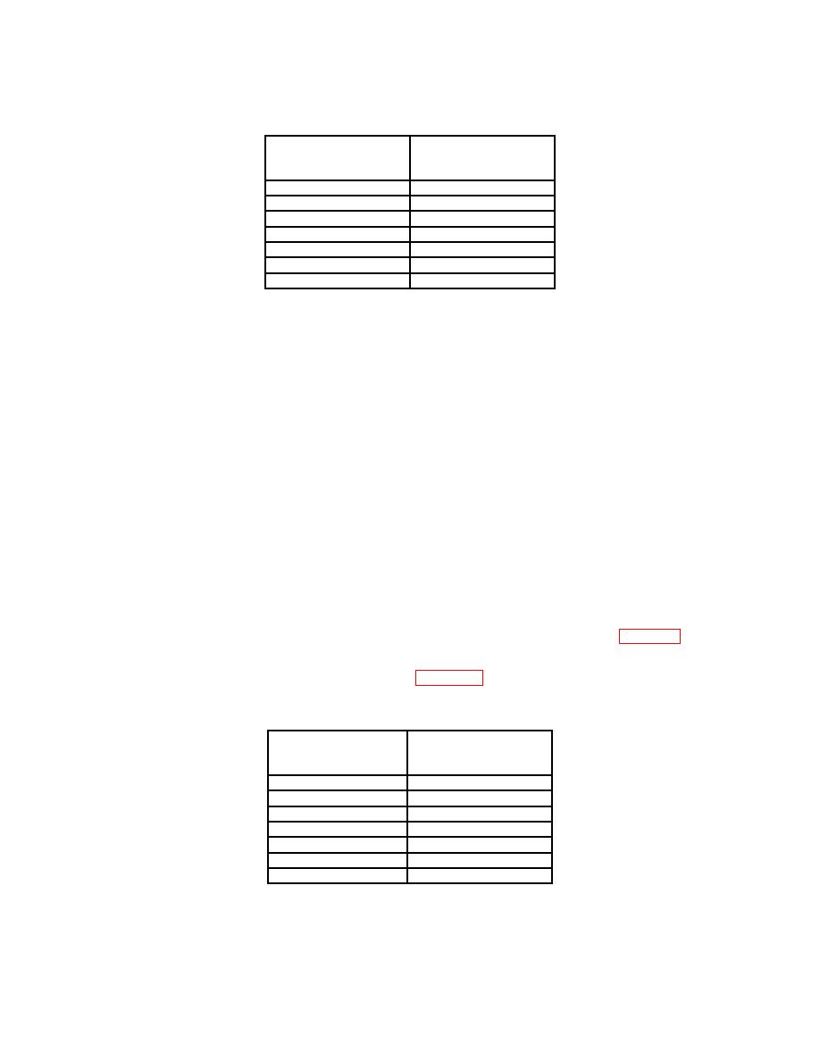
Test instrument
Oscilloscope
CAL 02
calibrator output
step numbers
settings
113,114
.5 V
1
115
.2 V
116
.1 V
117
50
mV
118
20
mV
119
1
V
120
10
V
1When
step 113 is performed, step 114 is automatically
done. No indication of step 114 will be shown unless
a LIMIT error is encountered.
(11) After step 120 is performed display readout will indicate MOVE SW, CENTER
CH 2 POS step 121, 500 mV, 500 mV, and BWL.
(12) Move connection from CH 1 to CH 2.
(13) Set oscilloscope calibrator for a CHAN 1, VOLTAGE mode output of .5 V at
1 kHz frequency.
(14) Push up and release TRIGGER COUPLING switch.
(15) Adjust CH 2 VERTICAL POSITION control until CH 1 input coupling 1 M Ω DC
indicator remains illuminated, then push up and release TRIGGER COUPLING switch.
(16) Display readout will indicate MOVE SW, CENTER CH 2 POS step 122, 500
mV, 500 mV and BWL.
(18) Push up and release TRIGGER COUPLING switch.
(19) Adjust CH 2 VERTICAL POSITION control until CH 1 input coupling 1 M Ω DC
indicator remains illuminated, then push up and release TRIGGER COUPLING switch.
(20) Display readout will indicate first CAL 02 step number listed in table 16, (123,
124).
(21) For each step number listed in table 16 apply corresponding calibration
generator output, then push up and release TRIGGER COUPLING switch.
Test instrument
CAL 02
Oscilloscope calibrator
Step numbers
output settings
123,124
.5
V
1
125
.2
V
126
.1
V
127
50 mV
128
20 mV
129
1V
130
10 V
1When
step 123 is performed, step 124 is also
automatically done. No indication of step 124 will be
shown unless a LIMIT error is encountered.
29

