
TB 9-6625-2294-35
NOTE
Press oscilloscope calibrator CHANNEL pushbutton. Next
press blue soft pushbutton located below CHAN 1 on
oscilloscope calibrator when SELECT CHANNEL is displayed.
(33) Set oscilloscope calibrator VOLTAGE output to as listed in first row of table 9 at
1 kHz.
(34) Press TI pushbuttons for indications as listed in (a) through (e) below:
(a)
VERTICAL MODE CH 1 on.
(b)
VERTICAL MODE CH 2, CH 3, and CH 4 off.
CH 1 input coupling pushbutton to 1 MΩ DC.
(c)
(d)
TRIGGER SOURCE upper to select VERT CH 1.
∆V to indicate ∆V (horizontal cursors on).
(e)
(35) Set CH 1 VOLTS/DIV switch as listed in first row of table 9 and adjust CH 1
(36) Adjust ∆REF OR DLY POS control to align reference cursor with bottom of
waveform.
(37) Adjust ∆ control to align delta cursor with top of waveform. If ∆V readout
indications do not indicate within limits as listed in first row of table 9, perform b below.
(38) Repeat technique of (33) through (37) above for remaining rows in table 9. ∆V
readout will indicate within limits listed in table 9.
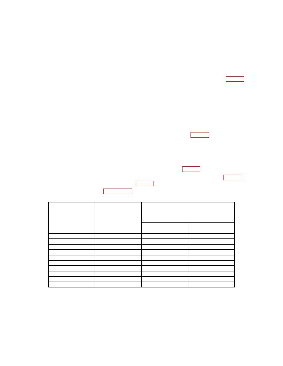
Table 9. ∆V with Cursors
Oscilloscope
Test instrument
Calibrator
Test instrument
VOLTAGE
VOLTS/DIV
∆V readout indications
switch settings
output settings
Min
Max
2
mV
10
mV
9.81
mV
10.2
mV
5
mV
20
mV
19.6
mV
20.4
mV
10
mV
50
mV
49.0
mV
50.9
mV
20
mV
0.1
V
98.1
mV
102.0
mV
50
mV
0.2
V
196
mV
204
mV
100
mV
0.5
V
490
mV
509
mV
200
mV
1.0
V
.981 mV
1.02
mV
500
mV
2.0
V
1.96
V
2.04
V
1.0
V
5.0
V
4.90
V
5.09
V
2.0
V
10.0
V
9.81
V
10.2
V
5.0
V
20.0
V
19.6
V
20.4
V

