
TB 9-6625-2309-35
NOTE
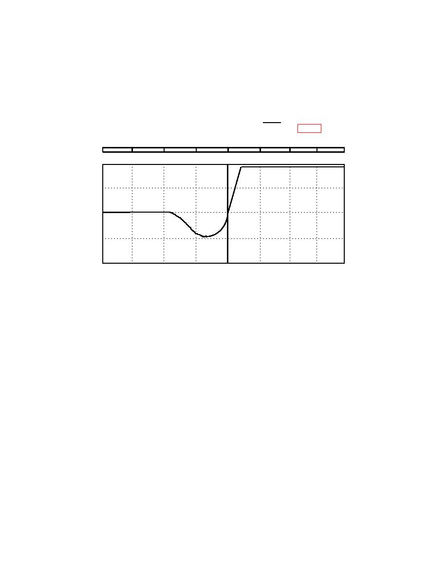
Accurate cursor placement to correct position on pulse starting
point is required for good results. Some optical modules have
been observed to display undershoot on trace prior to FOCUS
pulse. If there is undershoot, adjust cursor to immediate
beginning of FOCUS generated pulse after undershoot so
undershoot is just below horizontal center graticule (fig. 6).
0 km
65 km
131 km
A
100. 0059
100. 0219
100. 0379
↑
0.0040 km / div →
.25 dB / div
A = 100. 0220 km
INDEX: 1. 4990
B = 117. 4766 km
λ: 1310 SM
A→B = 17. 4546 km
PW: 8.00 s
# AVG = 4, 096. 0
2-POINT LOSS: 20. 56 dB
(12) Record A= (in km) on TI display in A= (km) column on TD-260C Horizontal Scale
Data Sheet (appendix A).
NOTE
Each change in digital delay/pulse generator A= T+ value will
not produce a change in position of FOCUS generated pulse.
Normally a series of A= T+ values, incremented in small
constant positive steps, will result in same pulse positions up
to a point. At this point the next A=T+ increment will cause
pulse to shift to right of the cursor on TI display. This
procedure requires the lowest A=T+ value which causes the
FOCUS generated pulse to shift in position, resulting in a
larger A= T+ indication. One shift is required for each cluster
of data. When this shift occurs, no more data is required for
that cluster. Shift magnitude will typically be 0.5 meter for
first cluster (all optical modules); 2 meters for TD-260C, 4
meters for TD-261C, and 8 meters for TD-285C for second
cluster.
13

