
TB 9-6625-2332-50
(12) Connect TI 9211 module OUTPUT (upper BNC connector) to the open end of the
BNC tee adapter on the front of the multimeter.
(13) Press TI pushbuttons as listed in (a) through (f) below:
(a)
CHANNEL A.
(b)
(c)
(d)
Trigger-Mode and repeatedly press ENTER/HZ until EXT. WIDE mode is
selected.
(e) Trigger slope ( - ).
(f) DISABLE (model 9211 output module) to on (red light extinguished).
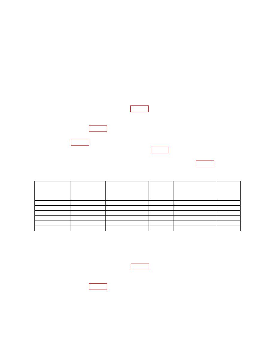
(14) Record multimeter indication in table 4 under actual multimeter reading for
Vhigh setting.
(15) Multiply the actual multimeter reading, times the termination correction factor,
and record the results in table 4.
(16) Verify that the value recorded in (15) above is within limits specified for the
(17) Set TI to the next Vhigh setting listed in table 4 and repeat (14) through (16)
above.
(18) Repeat (17) above for the remaining Vhigh settings listed in table 4.
Multimeter
Test
indication X
Termination
instrument
Vhigh
termination
correction
Multimeter
setting
Max
correction factor
Min
factor
indication
5.0
4.86
5.14
3.0
2.9
3.1
1.0
.94
1.06
0.5
0.45
0.55
0.3
0.254
0.346
0.1
0.058
0.142
(19) Press TI pushbuttons as listed in (a) through (c) below:
(a) Vhigh and enter 0 from data keyboard and press ENTER/HZ.
(b) Vlow and enter -5 from data keyboard and press ENTER/HZ.
(c) TRIGGER SLOPE POSITIVE.
(20) Record multimeter indication in table 5 under actual multimeter reading for
Vlow setting.
(21) Multiply the actual multimeter reading times the termination correction factor
and record the results in table 5.
7

