
TB 9-6625-2337-35
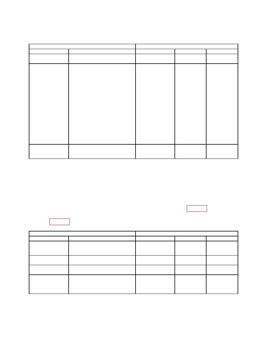
Table 31. Azimuth Gate Characteristics - Continued
TI
Oscilloscope
Test description
Settings
Measurement type
Minimum
Maximum
AZIMUTH
----------------------------------------
Width of pulse
250.2 ms
305.8 ms
train on channel 2
Press FUNC, ↑
1.350 s
1.650 s
Delta time
AZIMUTH GATE
Channel 1 to
1500 ms
14, ENTR (PRF/PRI)
channel 2 first
Use the arrow keys to highlight
pulses
PRF:
300, ENTR (300 PPS)
Press FUNC, ↑
9, ENTR (ACTIVE GATING)
Use the arrow keys to highlight
Ant. Rate:
4000000, ENTR (4,000,000 s)
Use the arrow keys to highlight
AZ GATE START:
135, ENTR (135)
Use the arrow keys to highlight
AZ GATE WIDTH:
3, ENTR (3.0)
AZIMUTH
----------------------------------------
Width of pulse
29.7 ms
36.3 ms
WIDTH
train on channel 2
33 ms
(7) Move connection from RADAR SIM POS READOUT GATE to TRIGGERS
0 OUT.
(8) Move connection from RADAR SIM NORTH TRIGGER OUT to RADAR SIM
POS READOUT GATE.
(9) Adjust the oscilloscope to trigger on channel 1 with channel 2 pulse displayed to
the left of the pulse on channel 1. Set oscilloscope to measurement type to delta time.
(10) Oscilloscope will indicate within limits listed in first row of table 32.
(11) Repeat technique of (3) through (5) above using remaining setting and limits
listed in table 32.
TI
Oscilloscope
Test description
Connections
Measurement type
Minimum
Maximum
AZIMUTH GATE
----------------------------------------
Delta time
270 s
330 s
300 ms
Channel 2 to
channel 1 pulse
POS READOUT
----------------------------------------
Width of pulse on
270 s
330 s
PW
channel 1
POS READOUT
----------------------------------------
V Top
15 V
25 V
AMP
Delta time
270 s
330 s
AZIMUTH GATE
Move the connection from the
Channel 2 to
RADAR SIM POS READOUT
channel 1 pulse
GATE to the RADAR SIM NEG
READOUT GATE.
43

