
TB 9-6625-2340-24
(9) Replace screws over A22 adjust.
(10) Replace TI bottom cover.
(11) Reconnect cable between FREQ REFERENCE INT and EXT connectors.
b. Adjustments. No further adjustments can be made.
9. Calibrator Amplitude
a. Performance Check
(1) Connect measuring receiver sensor module to measuring receiver power
reference output.
(2) Zero and calibrate the sensor module.
(3) Disconnect sensor module from measuring receiver power reference output.
(4) Connect measuring receiver sensor module to TI CAL OUTPUT.
(5) Set up measuring receiver to measure power at 100 MHz. If displayed power
measurement is not within the limits specified in table 3, perform b below.
Table 3. Calibrator Amplitude
Measuring receiver indications
Test
(dBm)
instrument
Min
Max
10.3
9.7
Cal output
b. Adjustments
(1) Set LINE switch to STANDBY.
(2) Position TI on its right side.
(3) Remove TI bottom cover.
(4) Set LINE switch to ON.
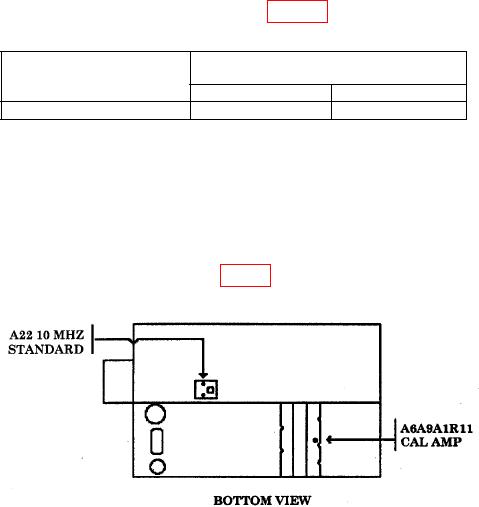
(5) Adjust A6A9A1R11 CAL AMP. (fig. 2) for a measuring receiver indication of 10
0.01 dBm (R).
Figure 2. Calibrator amplitude adjustment.
(6) Set LINE switch to STANDBY.
(7) Replace TI bottom cover.
(8) Set LINE switch to ON.

