
TB 9-6625-2340-24
(2) Set up multimeter to measure V dc.
(3) Press TI keys as listed in (a) through (c) below:
(a) 2-22 GHz.
(b) FREQUENCY SPAN, 0, Hz.
(c) CENTER FREQUENCY, 0, Hz.
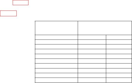
(4) The reading indicated on multimeter will be within limits specified in the first
row of table 53.
(5) Repeat technique of (3) (c) and (4) above for remaining frequencies listed in
Table 53. Sweep and Tune Out
Multimeter
Test
Indication
instrument
(Vdc)
Frequency
Min
Max
0.01
0
Hz
0.01
0.11
1
MHz
0.009
0.022
0.002
12
MHz
0.143
0.117
130
MHz
0.693
0.647
670
MHz
1.336
1.264
1.3
GHz
5.824
5.576
5.7
GHz
12.76
12.24
12.5
GHz
18.37
17.63
18
GHz
(6) Disconnect TI SWEEP + TUNE OUT (rear panel) from multimeter INPUT.
b. Adjustments. None.
27. Fast Sweep Time Accuracy
a. Performance Check
(1) Connect TI RF INPUT to signal generator RF output connector.
(2) Connect function generator UNBALANCED output to signal generator
amplitude modulation input connector.
(3) Press TI 2-22 GHz key.
(4) Set signal generator for an output frequency of 500 MHz and an output
level of 10 dBm.
(5) Press TI keys as listed in (a) through (e) below:
CENTER FREQUENCY, 500, MHz.
(a)
FREQUENCY SPAN, 100, kHz.
(b)
MARKER NORMAL.
(c)
MARKER PEAK SEARCH.
(d)
MARKER CF.
(e)
(6) Set function generator for a triangle wave output at a frequency of 2 kHz, an
amplitude of 1 V, and 50 impedance.

