
TB 9-6625-2346-35
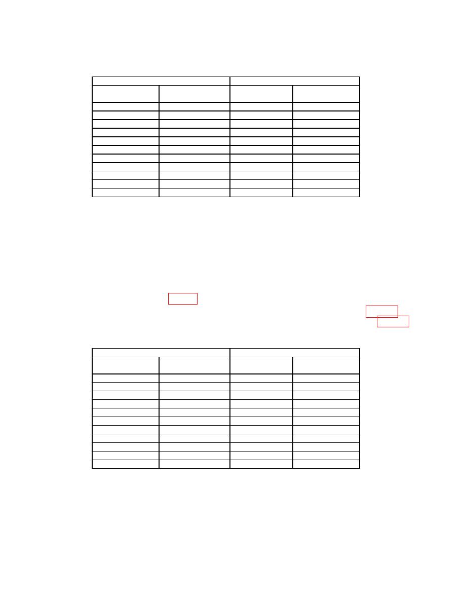
Test instrument
Oscilloscope calibrator
VOLTS/DIV
Divisions of vertical
VOLTAGE
Err display
setting
deflection
output
Indication (%)
2
m
5
10 mV
2
5
m
4
20 mV
2
10
m
5
50 mV
2
20
m
5
.1 V
2
50
m
4
.2 V
2
.1
5
.5 V
2
.2
5
1V
2
.5
4
2V
2
1
5
5V
2
2
5
10 V
2
5
4
20 V
2
(7) Set oscilloscope calibrator output to standby.
(8) Set TI CH 2 VOLTS/DIV switch to 2m.
(9) Set oscilloscope calibrator CH 2 for a VOLTAGE output of 10 mV at 1 kHz.
(10) Adjust TI A TRIGGER LEVEL and POSITION controls as necessary to view
(11) Rotate oscilloscope calibrator knob located below EDIT FIELD key for 5
divisions of vertical display. If oscilloscope calibrator Err display does not indicate within
limits specified in first row of table 4, perform b (41) through (82) below.
(12) Repeat technique of (8) through (11) above for settings listed in table 4. If
oscilloscope calibrator Err display does not indicate within limits specified in table 4,
perform b (41) through (82) below.
Test instrument
Oscilloscope calibrator
VOLTS/DIV
Divisions of vertical
VOLTAGE
Err display
setting
deflection
output
Indication (%)
2m
5
10 mV
2
5m
4
20 mV
2
10 m
5
50 mV
2
20 m
5
.1 V
2
50 m
4
.2 V
2
.1
5
.5 V
2
.2
5
1
V
2
.5
4
2
V
2
1
5
5
V
2
2
5
10
V
2
5
4
20
V
2
(13) Set oscilloscope calibrator output to standby.
(14) Connect oscilloscope calibrator SOURCE/MEASURE CHAN 1 through a 50Ω
feed through termination to TI CH 1 input and oscilloscope calibrator
SOURCE/MEASURE CHAN 2 through a 50Ω feed through termination to TI CH 2 input.
(15) Position TI switches as listed in (a) through (c) below:
7

