
TB 9-6695-288-35
(8) Set spectrum analyzer controls as indicated in (a) through (g) below.
(a) Press INSTR PRESET.
(b) Press INPUT ENTRY RANGE and STEP pushbuttons to step range to
+25 dBm.
(c) Press INPUT IMPEDANCE 1 MΩ pushbutton to on.
(d) Enter REFERENCE LEVEL +15 dBm.
(e) Enter CENTER FREQUENCY 1kHz.
(f) Enter FREQUENCY SPAN 10Hz.
(g) Enter dB/DIV 1dB.
(9) Adjust marker on spectrum analyzer to peak of signal.
(10) Set reference on spectrum analyzer by pressing MARKER OFFSET and
ENTER OFFSET pushbuttons.
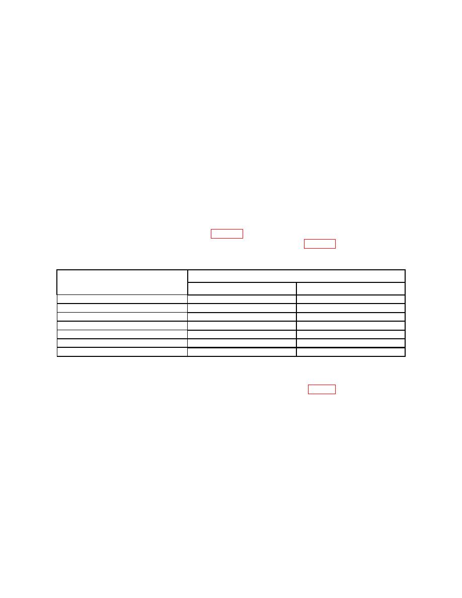
frequency to each frequency listed in table 9, and repeat (9) above. Offset amplitude
readings on spectrum analyzer will be within limits listed in table 9. If not, perform b
below.
Spectrum analyzer offset indications (dB)
Function/arbitrary generator settings
Min
Max
10 Hz
-2
+1
20 Hz
-1
+1
100 Hz
-1
+1
20 kHz
-1
+1
50 kHz
-2
+1
100 kHz
-4
+1.5
330 kHz
-4
+1.5
b. Adjustments
(1) Adjust A3C18 NOTCH FILTER HIGH FREQ. ADJ. (fig. 1) for an indication
between -1 dB and +1 dB (R).
15. Final Procedure
a. Deenergize and disconnect all equipment.
b. Annotate and affix DA label/form in accordance with TB 750-25.
17

