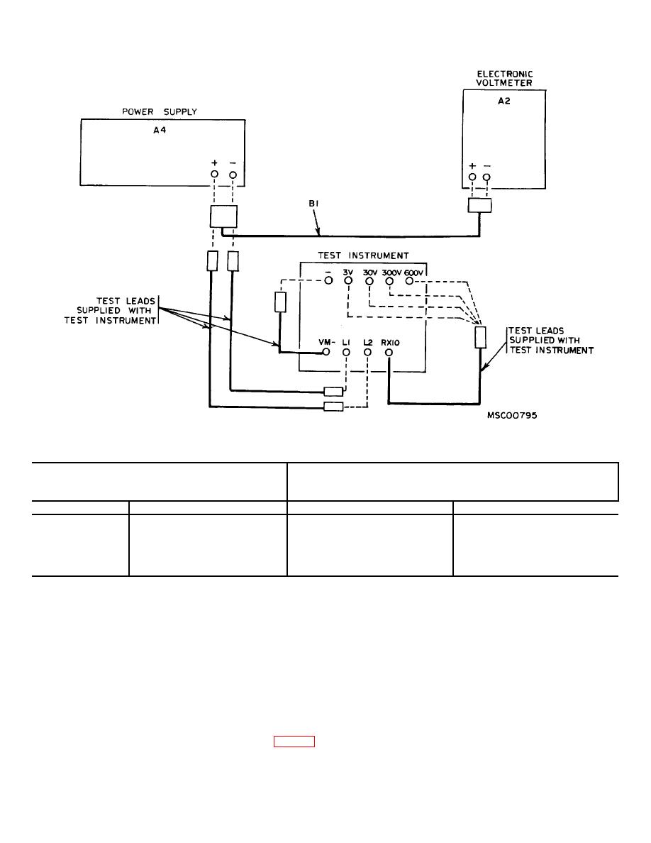
Figure 1. Voltmeter accuracy check, equipment setup.
Table 4. Voltmeter Accuracy
Test instrument
Electronic voltmeter or meter calibrator
Range
Indication
min
max
30V
10NV
9.1
10.9
30V'
20V
19.1
20.9
30V
30V
29.1
30.9
300V*
300V
291.0
309.0
600V*
500V'
482.0
518.0
*Use Power Supply (AR) in place of (A4) for this check
NOTE
9. Resistance Accuracy. a. Performance Check.
Perform procedures given in (5) through (7) below
for AN/GSM-256 calibration.
NOTE
(5) Connect meter calibrator (A3) - (negative)
Substitute equipment in parentheses for AN/GSM-
terminal to TI L1 and +(positive) terminal to L2, using leads
256 calibration.
furnished with TI.
(1) Position controls and test leads on TI as in (a)
(6) Connect TI RX10 terminal to TI 3V range and
through (c) below:
'VM-terminal to TI-. Adjust meter calibrator for a 3-volt
(a) VM-RES Switch to RES.
indication on TI meter. Meter calibrator will indicate
(b) RX10 test lead to R jack.
between 2.91 and 3.09 volts dc.
(c) VM test lead to X jack.
(7) Repeat the procedures given in (6) above for TI
(2) Connect L1 and L2 on TI to decade resistor (A1)
range positions and meter indications listed in table 4.
(meter calibrator A3) using leads furnished with TI.
Meter calibration will indicate within limits specified.
(3) Set decade resistor (meter Calibrator) controls
b. Adjustments. No adjustments can be made.
4


