
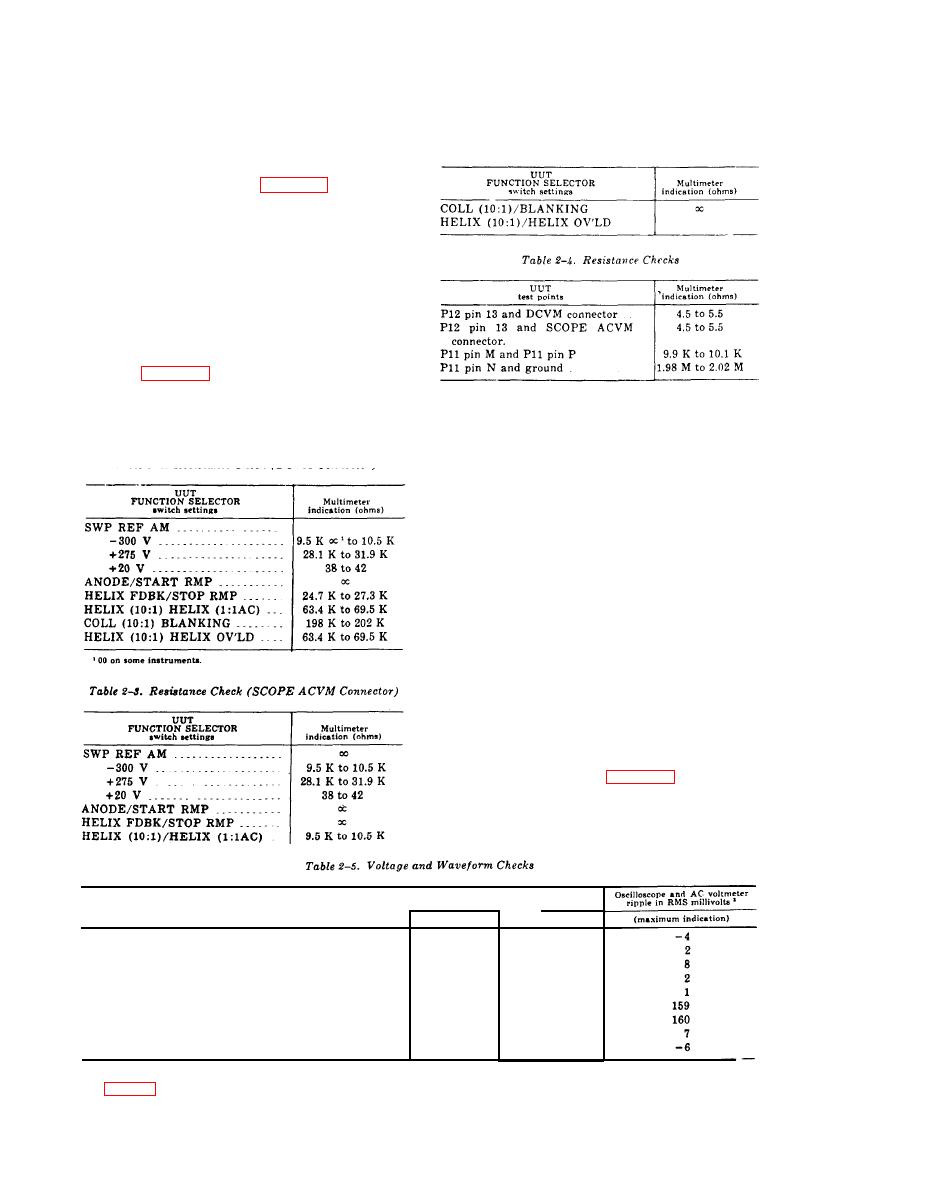
(4) Set UUT FUNCTION SELECTOR
switch to settings listed in table 2-3. Multimeter
indicates with specified limits.
(5) Set UUT FUNCTION SELECTOR
switch to HELIX (10:1) /HELIX (1:1AC).
(6) Reverse banana plugs on multimeter.
(7) Multimeter indicates between 2K ohms
and 4K ohms.
(8) Set UUT FUNCTION SELECTOR
switch to - 6.3V
(9) Connect multimeter to UUT test points
listed in table 2-4, with 2 test leads (1-9) and
2 probes (1-10). Multimeter indicates within
specified limits.
NOTE
Install UUT in sweep oscillator (1-5).
b. Adjustments. No adjustments can be made.
a. Performance Check.
(1) Connect voltmeter (1-2) to UUT DC-
VM jack with cable assembly (1-7).
(2) Connect UUT SCOPE ACVM jack to
oscilloscope channel A input using a connector
(1-8) and cable assembly ( 1-7). Connect cable
assembly (1-7) from connector (1-8) to volt-
meter (1-4).
(3) Turn sweep oscillator (1-5) LINE
switch to STANDBY and allow approximately
1 minute for equipment warmup.
(4) Depress UUT TIME DELAY OVER-
RIDE pushbutton for about 5 seconds.
(5) Turn sweep oscillator LINE switch to
RF.
(6) Set UUT FUNCTION SELECTOR
switch to positions listed in table 2-5 and observe
that the indications are within the prescribed
limits.
b. Adjustments. No adjustments can be made.
Voltmeter indication
(vol-- .
ts)
UUT FUNCTION SELECTOh
switch position
minimum
maximum
I
SWP REF AM
+40
+36
-300 -300. . . . . . . . . . . . . . . . . . . . . . . . . .
-280
-320
-6.3V-6.3V . . . . . . . . . . .. . . . . . . . . . . . . . . . . . . . . . .
-6.5
-6.1
+ 276V + 275V
+ 294
.
+ 256
+20V/+20V . . . . . . . . . . . . . . . . . . . . . . .
+21
+19
ANODE/START RMP . . . . . . . . . . .
+ 104
+ 116
HELIX FDBK STOP RMP
+ 33.3
+ 37.31
.
HELIX (10:1) /HELIX (1:1AC)
+124 3
+112
COLL(10:1) BLANKING . . . . . .
..
+ 136.5
+118
1
Note this Indicatlon.
2
Add 12.6 volts to the HELIX (10:1) HELIX (1:1 AC) voltage.
3
See figure 2-1 for typical oscilloscope presentation.
12
