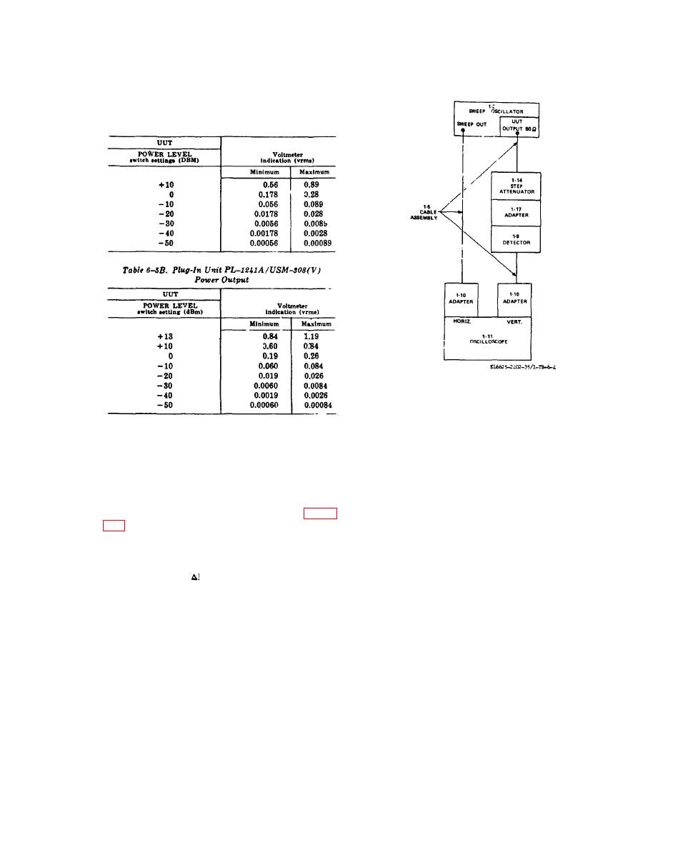
Table 6-5A. Plug-In Unit PL-1241/USM308(V)
Power Output
two step attenuator settings. This calibrates os-
(5) Repeat (1) through (4) above until no
cilloscope for 0.25 db/cm vertical deflection. Do
further adjustment is required.
not move oscilloscope vertical controls for re-
(6) Repeat performance check,
mainder of check.
(6) Set step attenuator switch to 10 db (3
6-8. Flatness
db for PL-1241A/USM-308 (V))
(7) Position sweep oscillator controls as fol-
a. Performance Check.
lows:
(1) Connect equipment as shown in figure
(a) SWEEP SELECTOR switch to AU-
TO.
(2) Position sweep oscillator controls as fol-
(b) START/CW control to 10.
lows:
(8) Adjust oscilloscope horizontal gain con-
(a) START/CW control to 40.
trols for 10 cm trace. Difference between maxi-
(b) STOP/ F control to 110.
mum and minimum vertical deflection points is
(C) FUNCTION START-STOP pushbut-
less than 2.4 cm peak-to-peak.
ton pressed.
(9) Set UUT SCALE switch to X1.
(d) SWEEP TIME (SEC) switch to .1-
(10) Repeat step (8) above.
.01.
(11) Disconnect equipment.
(e) SWEEP SELECTOR switch to CW.
b. Adjustments. No adjustments can be made.
(3) Position UUT controls as follows:
(a) SCALE switch to X1.
(b) POWER LEVEL switch to +10 dbm
(0 dbm on PL-1241A/USM-308 (V).
a: Performance Check.
(c) VERNIER control to CAL.
(1) Connect multimeter (1-15) to UUT
(4) Adjust oscilloscope controls for display
SWEEP REF connector (rear panel) with cable
of free running sweep.
assembly (1-5) and adapter ( 1-10).
(2) Position sweep oscillator controls as fol-
(5) Alternately set step attenuator (1-14)
lows.
switch from 10 to 1.1 db (3 to 4 db for PL-1241A/
(a) FUNCTION START-STOP pushbut-
USM-308(V) ) and adjust oscilloscope vertical
ton pressed.
controls for 4 centimeter deflection between the
37


