
(b) SWEEP SELECTOR switch to MAN-
(b) SWEEP SELECTOR switch to
MANUAL.
UAL.
(c) START/CW control to 10.
(c) START/CW control to 1 (4 on PL-
(d) STOP/AF control to 110,
1241A/USM-308(V)).
(d) STOP/AF control to 110.
(3) Set UUT SCALE switch to X.1.
(3) Set UUT SCALE switch to X.1.
( 4 ) Turn sweep oscillator MANUAL
SWEEP control fully counterclockwise.
( 4 ) Turn sweep oscillator MANUAL
SWEEP control from limit to limit. Power meter
(5) Multimeter indicates between 0.8 and
indicates greater than -15 dbm (0.03 mw for
1.2 vdc.
PL--1241A/USM-308(V)).
( 6 ) Turn sweep oscillator MANUAL
(5) Set UUT SCALE switch to X1 and re.
SWEEP control fully clockwise.
peat step (4) above.
(7) Multimeter indicates between 10. and
b. Adjustments. No adjustments can be made.
12 vdc.
(8) Set UUT SCALE switch to X1.
(9) Repeat steps (4) through (7) above.
a. Performance Check,
b. Adjustments. No adjustments can be made.
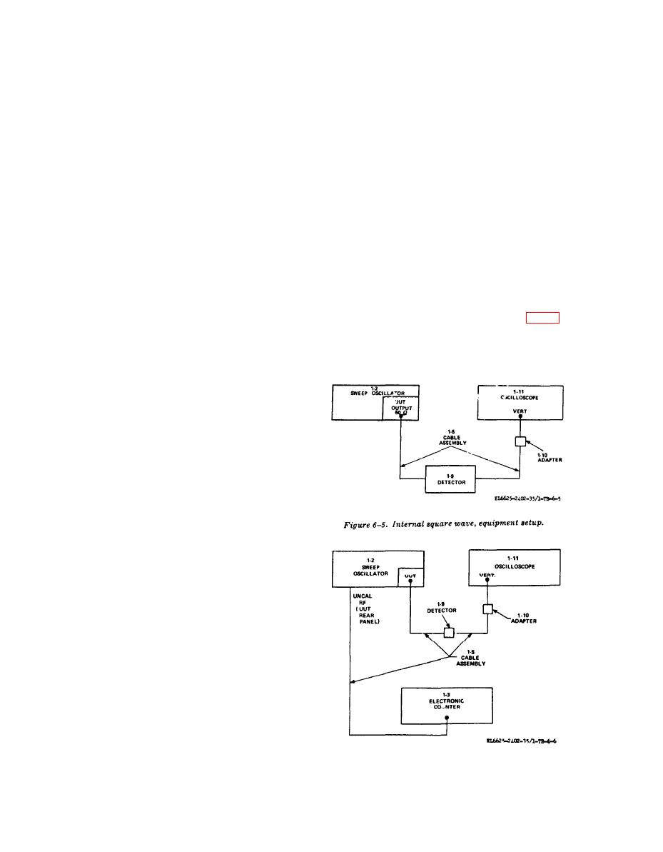
(1) Connect equipment as shown in figure
6-5.
(2) Position sweep oscillator controls as fol-
lows:
a. Performance Check.
(a) SWEEP SELECTOR switch to CW.
(1) Connect power meter (1-16) thermistor
mount to UUT AUX OUTPUT connector (rear
panel) with adapter (1-8).
(2) Position sweep oscillator controls as fol-
lows:
(a) START/CW control to 100.
(b) FUNCTION START-STOP push-
button pressed.
(c) SWEEP SELECTOR switch to CW.
(d) All AMPLITUDE MOD pushbut-
tons released.
(3) Set UUT SCALE switch to X.1.
(4) Power meter indicates greater than
-15 dbm (0.3 mw for PL-1241A/USM-308(V)).
(5) Set UUT SCALE switch to X1.
(6) Power meter indicates greater than
-15 dbm (0.3 mw for PL-1241A/USM-308-
(V)).
(7) Disconnect equipment .
b. Adjustments. No adjustments can be made.
a. Performance Check.
(1) Connect power meter thermistor mount
to UUT V.T.O. OUTPUT connector (rear panel)
with adapter (1-8).
(2) Position sweep oscillator controls as
follows:
(a) FUNCTION START-STOP pushbut-
ton pressed,
