TB 11-6625-2734-50
SECTION IV
CALIBRATION PROCESS
head used and may not be properly
NOTE
adjusted for other sampling heads.
Unless otherwise specified,
verify the results of each test
and take corrective action
(3) Depress oscilloscope (A3) right vertical
whenever
the
test
mode switch and right vertical trigger source switch.
requirement is not met before
(4) Adjust TI DC OFFSET control to display
continuing
with
the
pulse on oscilloscope crt. If step is off oscilloscope crt,
perform b(1) below.
(5) Adjust TI mV/DIV VARIABLE control for a 5-
8. Memory Gate Width and Gain. a. Performance
division step on oscilloscope crt. If first dot is not 4.5
Check.
divisions above 0-percent level on oscilloscope crt
display, perform b(2) and (3) below.
(1) Connect pulse generator (A4) PULSE
(6) Turn TI mV/DIV VARIABLE switch to CAL IN
OUTPUT to sampling head (A7) lower input, using cable
and remove coaxial line from sampling head input and
(B6).
pulse generator output.
(2) Connect termination (B11) to sampling head
b. Adjustments.
upper input.
(1) Adjust R592 (fig. 2) until pulse is displayed
NOTE
on oscilloscope crt.
TI memory gain is adjusted to
compensate for gain of sampling
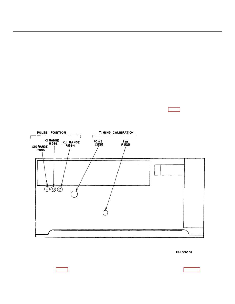
Figure 1. Adjustment locations on right index card.
(2) Adjust R390 (fig. 2) to raise dot above step 0
100 percent level.
Refer to figure 3 for similar
percent level to its maximum amplitude (may overshoot
waveform).
5


