
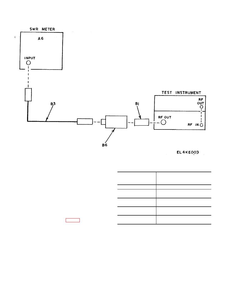
Figure 3. Attenuator accuracy--equipment setup.
(2) Adjust signal source ATTENUATOR
Table 7. Attenuation Check
control for CAL indication on power monitor meter.
Test instrument
(3) Set
doubler
POWER
POWER OUTLET
OUTPUT attenuator for 0 dBm (Approach this point from
attenuator settings
SWR meter indications
the mechanical stop above the attenuator).
(-dBm)
(dB)
(4) Adjust signal source for square wave
5
4.8 to 5.2 (4.5 to 5.5 from 10.0
modulation and 5.0 GHz.
to 10.8 GHz)
(5) Adjust SQ WAVE control for peak
10
9.8 to 10.2 (9.5 to 10.5 from
indication on SWR meter (A6).
10.0 to 10.8 GHz)
(6) Adjust SWR meter for a reference
15
14.7 to 15.3 (14.5 to 15.5 from
indication.
10.0 to 10.8 GHz)
(7) Set frequency double POWER OUTPUT
20
19.6 to 20.4 (19.5 to 20.5 from
attenuator to settings listed in table 7 or 8 (approach
10.0 to 10.8 GHz)
settings from the mechanical stop above the attenuator).
(8) Repeat (1) through (7) above for 5.6,
SWR meter indications will be within the limits specified.
6.2, and 7.0 GHz signal source frequencies.
7
