TB 3-6665-314-50
Table 4. Pressure Gage Performance Limits
Scale major Division Indication
Acceptable Manometer Indications
(inches of water
Min.
Max.
5
4.5
5.5
10
9.5
10.5
15
14.5
15.5
20
19.5
20.5
25
24.5
25.5
8. PRESSURE Gage. a. Performance Check.
CAUTION
(1)
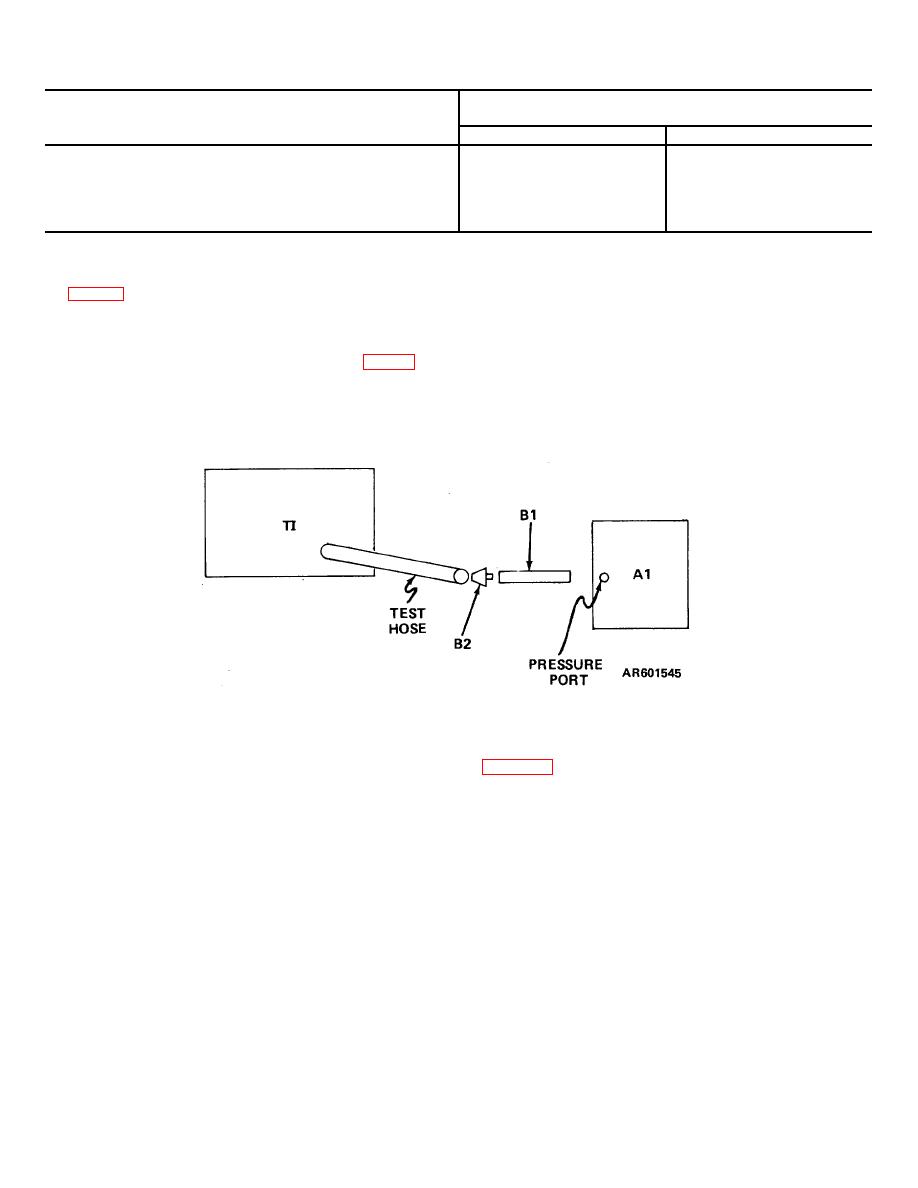
Connect the test equipment as shown
Since a sudden change in pressure
in figure 3.
could damage the TI, do not
(2)
Close valve (B1).
disconnect the equipment before
(3)
Slowly turn BLEED VALVE clockwise
returning the TI to atmospheric
until the PRESSURE gage pointer is at "5" on the scale.
pressure.
The manometer (Al) must indicate as shown in table 4.
(4)
Repeat (3) above for each major
(5)
After the performance is completed,
division, (cardinal point) in the PRESSURE gage scale.
slowly open the BLEED VALVE to return the TI to
atmospheric pressure.
b. Adjustments. No adjustments can be made.
Figure 3. PRESSURE gage performance check, equipment setup.
the TI does not indicate within the limits specified in
9. Final Procedure. a. Deenergize and disconnect all
equipment.
(Unserviceable or Limited Use) tag.
b. In accordance with TM 38-750, annotate and
affix DA Label 80 (US Army Calibration System). When
By Order of the Secretary of the Army:
BERNARD W. ROGERS
General, United States Army
Chief of Staff
Official:
PAUL T. SMITH
Major General, United States Army
The Adjutant General
DISTRIBUTION:
To be distributed in accordance with DA Form 12-34A, Requirements for Calibration Procedures Publications.
*U.S. GOVERNMENT PRINTING OFFICE: 1977-765010/534
4


