
TB 9-4920-364-24
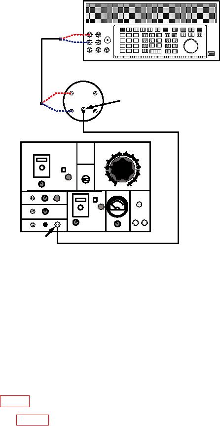
BH 277
BH 123-3
JETCAL
P1
P3
P2
S1
S2
BH 450
CHECK CABLE
Figure 1. Potentiometer - equipment setup.
(2) Place thermometer near the output of calibrator. Wait 10 minutes and record
temperature.
(3) Position controls as listed in (a) through (c) below:
(a) SELECTOR SWITCH SW-1 to T/C.
(b) SW-5 switch (located on BH 123-3) to JETCAL.
(c) THERMOCOUPLE CHECK SW-2 switch to S-2.
(4) Adjust GALVO-1 MECH. ZERO control until GALVO-1 indicates 0. Repeat as
necessary throughout procedure.
(5) Adjust C control for a 0 dial indication.
NOTE
Throughout this procedure it will be necessary to constantly
check the ambient temperature to assure that millivolt values
in table 3 are applicable.
(6) Refer to table 3 and adjust calibrator to millivolt value corresponding to
temperature recorded in (2) above.
5