
TB 9-4920-454-24
WARNING
115 V ac potential exists between pin A and/or B of the
HEATER CABLE connector and ground when MASTER
POWER switch is in the OFF position and when power cable
is connected to ac source.
DEATH ON CONTACT and
destruction of calibrator may result if personnel fail to observe
safety precautions.
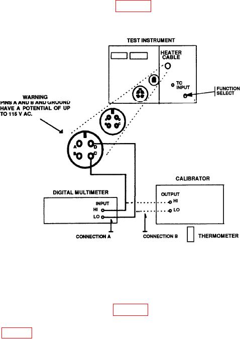
(4) Connect equipment as shown in figure 8, CONNECTION A. Set multimeter for
ac voltage measurements.
Figure 8. Heater probe.
(5) Reconnect power cable to 115 V ac source and set MASTER POWER switch to ON.
(6) Multimeter should indicate 0 V ac (1.0); if not, verify equipment connection.
(Ensure that pins C and D are connected to multimeter.)
(7) Connect equipment as shown in figure 8, CONNECTION B.
(8) Set calibrator for an dc millivolt output corresponding to ambient temperature
as specified in table 3.
(9) Set TEMPERATURE switch to HEATER PROBE TEMP SET.
13