
TB 9-4920-456-24
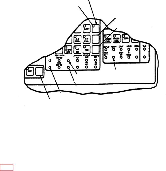
SPARE 3 KEY
SPARE 3
INDICATOR LIGHT
UNUSED KEY
SPARE 2 KEY
SPARE 6
SPARE 2
INDICATOR LIGHT
INDICATOR LIGHT
SPARE 1 INDICATOR LIGHT
SPARE 4 INDICATOR LIGHT
UNUSED KEY
Figure 1. Spare Indicator Location.
(9) Press EJECT key on TRANSPONDER CONTROL keyboard.
EJECT key
indicator light will be off and multimeter will indicate less than 0.4 V dc.
(10) Disconnect multimeter from calibration test fixture jacks.
(11) Set SELECT S1 switch on calibration test fixture to D.
(12) Set INPUT/OUTPUT S2 switch on calibration test fixture to positions listed in
table 7 to light corresponding indicator.
14