
TB 9-4920-464-24
(20) Calculate the difference of VCD, and VEF and verify that it is 0.000 V AC 0.015 V
AC. If reading is not within tolerance, perform b below.
VCD ― VEF = ________________
FUNCTION
SELECTOR
INTERNAL
J-BOX
REF.
(21) Turn
TI
switch
to
SIGNATURE.
DC on TI DC VOLTMETER and wait for display to stabilize.
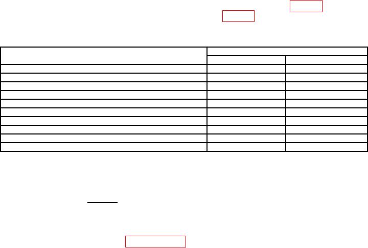
(23) Turn PARAMETER SELECTOR switch to settings listed in table 9 below. TI
meter readings will indicate within limits specified in table 9 below. If readings are not
within tolerance, perform b below.
Table 9. Internal and External J-BOX
PARAMETER SELECTOR
TI Meter readings
switch
MIN
MAX
IPRI
0.450
0.470
VPRI
90.0
100.0
VT
15.500
18.500
1
VC
15.100
18.100
1
VX
0.4000
0.5000
V01
5.043
5.083
V02
5.043
5.083
V03
5.043
5.083
< 0.35
>7.35
1 Record readings to obtain voltage ratio.
(24) Calculate the ratio using the following formula.
VX
VC =_________V DC
VX =_________V DC
V
VX
Ratio:____________
(25) Voltage ratio will be between 0.012902 and 0.013032.
b. Adjustments. Perform paragraph 14, Adjustment Procedure.
14. Adjustment Procedure
a. Turn TI
FUNCTION
SELECTOR
INTERNAL
J-BOX
REF.
switch
to
SIGNATURE.
b. Turn TI PARAMETER SELECTOR switch to V01.
c. Connect calibration fixture to TI connector J5. Set multimeter to read AC volts.
Connect multimeter to calibration fixture R1 and R2 to record readings as indicated below.
d. Turn TI POWER switch to ON and wait 60 minutes for TI to warm-up and stabilize.
NOTE
Ensure TI has had 60 minutes to warm-up and stabilize prior
to performing the following steps, otherwise readings could be
out of tolerance.