
TB 9-4920-464-24
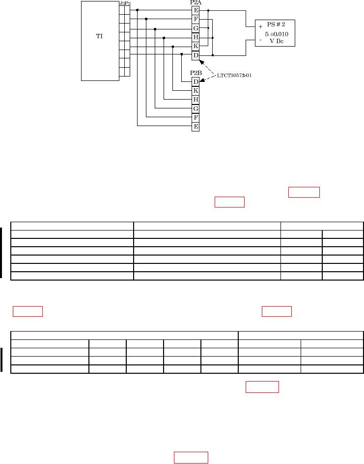
Figure 6. 5V DC test setup.
(17) Turn TI FUNCTION SELECTOR switch to AIRCRAFT SYSTEM TEST and
turn TI POWER switch to ON.
(18) Set power supply to 5 0.010 V dc.
(19) Turn PARAMETER SELECTOR switch to settings listed in table 7 below. TI
meter readings will indicate within limits specified in table 7 below.
Table 7. System Test 5 V dc
PARAMETER SELECTOR switch
Input from DC power supply
TI meter readings
V01
5V dc 0.010
04.980
05.020
V02
04.980
05.020
V03
04.980
05.020
V031
04.980
05.020
V02
04.980
05.020
V01
04.980
05.020
1 Turn TI FUNCTION SELECTOR switch to AIRCRAFT RDPS.
(20) Using the multimeter, measure the voltage for the cable and pins indicated in
Table 8. LTCT30572-01 5 V dc
TI
Multimeter reading V DC
Cable #
Plug #
Pin #
Plug #
Pin #
Min
Max
LTCT30572-01
P2B
E (+)
P2B
F (-)
04.980
05.020
P2B
G (+)
P2B
H (-)
04.980
05.020
P2B
K (+)
P2B
D (-)
04.980
05.020
(21) Turn off and disconnect power supply connected in figure 6 above.
(22) Disconnect cable LTCT30572-01 from TI.
b. Adjustments. No adjustments can be made.
12 Aircraft RDPS
a. Performance Check
(1) Connect equipment as shown in figure 7 below.
Change 1