
TB 9-4931-217-40
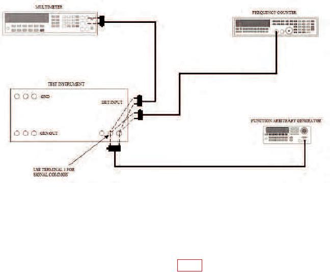
Figure 3. Ac detector sensitivity and selectivity - equipment setup.
(11) Remove frequency counter and cable from equipment setup and lead and
adapters connected in (2) above.
(12) Move cable from function/arbitrary generator output terminals and connect to
TI GEN OUTPUT terminals.
(13) Adjust GEN VOLTAGE control for half-scale indication on multimeter.
(14) Adjust FREQUENCY ADJ control (fig. 2) for peak indication on multimeter.
b. Adjustments. No further adjustments can be made.
14. Detector Sensitivity
a. Performance Check
(1) Connect TI DET INPUT and multimeter input terminals to function/arbitrary
generator output terminal.
(2) Turn GEN VOLTAGE control ccw but not to OFF.
(3) Adjust function/arbitrary generator controls for a 100 mV rms output with
frequency at 1 kHz.
(4) Adjust DET GAIN control for a convenient indication on TI null meter.
(6) Decrease function/arbitrary generator signal output level by 20 dB.
(7) Adjust DET GAIN control for an indication of 4 (full scale) on TI null meter.
DET GAIN control will be less than fully cw.