
TB 9-4931-321-24
four-to-one ratio between the standard and TI. Where the four-to-one ratio cannot be met,
the actual accuracy of the equipment selected is shown in parenthesis.
5. Accessories Required. The accessories required for this calibration are common
usage accessories, issued as indicated in paragraph 4 above, and are not listed in the
calibration procedure. The following peculiar accessories are also required for this
calibration: Termination (Dummy Load), 50
feedthrough; BNC plug to BNC jack,
Hewlett-Packard, Model 11048C (11048C) and Isolation Plug (three wire to two wire
adapter) (7912356).
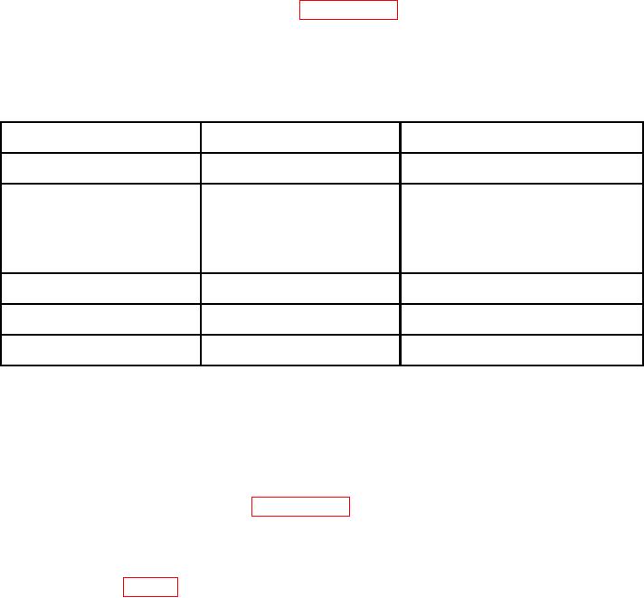
Table 2. Minimum Specifications of Equipment Required
Manufacturer and model
Common name
Minimum use specifications
(part number)
AUTOTRANSFORMER
Range: 105 to 125 V ac
Ridge, Model 9020A (9020A)
Accuracy: 1%
FUNCTION GENERATOR
Output Range: 0.015 to 1 V rms
Agilent, Model 33250A (33250A)
at 1 kHz
Accuracy: Amplitude 2%
Output Frequency: 890 to
1,020 Hz
Accuracy: 1%
Range: 0.87 to 1.8 V dc
Fluke, Model 8840A/AF05
Accuracy: 1%
(AN/GSM-64D)
RATIO TRANSFORMER
Range: 0.098850 to 1.000000
ESI, Model DT72A
Accuracy: 0.06%
(7915908)
Aange: 100 to 5,000
Biddle-Gray, Model 71-650 (71-650)
RESISTANCE STANDARD
R
ccuracy: +0.75%
CALIBRATION PROCESS
6. Preliminary Instructions
a. The instructions outlined in paragraphs 6 and 7 are preparatory to the calibration
process. Personnel should become familiar with the entire bulletin before beginning
the calibration.
b. Items of equipment used in this procedure are referenced within the text by common
name as listed in table 2.
c. Unless otherwise specified, verify the result of each test and, whenever the test
requirement is not met, take corrective action before continuing with the calibration.
Adjustments required to calibrate the TI are included in this procedure. Additional
maintenance information is contained in the manufacturer's manual for this TI.
d. Unless otherwise specified, all controls and control settings refer to the TI.