
TB 9-4931-321-24
(3) Set TI INPUT (INPUT SELECTOR) switch to LOW.
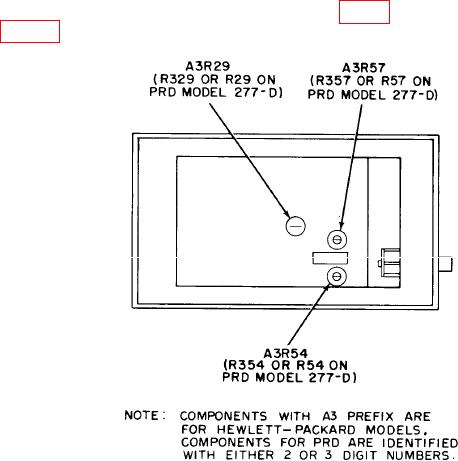
b. Adjustments. Adjust A3R54 (R354 or R54) (fig. 1) until all multimeter indications
listed in table 3 are within specified limits.
Figure 1. Standing wave ratio meter - left view.
9. Sensitivity, Stability and Noise
a. Performance Check
(1) Connect function generator to TI INPUT using 50
termination.
indication on TI meter.
(3) Adjust FREQ control for maximum meter indication.
If necessary, reduce
amplitude of function generator output.
(4) Adjust amplitude of function generator output for a 0 (zero) dB indication on TI
meter 0 (zero) to 10 dB scale.
(5) Function generator output will not exceed 0.15 V rms.
(6) Adjust autotransformer from 105 to 125 V, while maintaining 0 (zero) dB
indication on TI meter with amplitude control of function generator.
(7) Function generator output amplitude will not exceed 0.15 V rms.
(8) Adjust autotransformer for a 115 V output.
(9) Set INPUT (INPUT SELECTOR) switch to HIGH.