
TB 9-4931-405-40
8. Resistance
a. Performance Check
(1) Set multimeter for most accurate dc voltage measurements.
(2) Set calibrator for a nominal 10 A dc output.
(3) Allow sufficient time for stabilization (1 to 3 minutes), then record multimeter dc
voltage indication in table 3, section A. Calculate the calibrator's actual 10 A output using
the formula:
Multimeter indication (in V)
10 A Actual Output =
Test report value of standard resistor
(4) Record resulting value in table 3, section A, actual calibrator output column.
(5) Repeat technique of (2) through (4) above for remaining nominal calibrator
outputs listed in table 3, substituting standard resistors as specified.
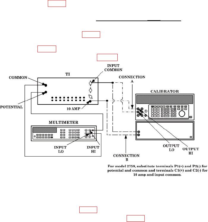
(6) Connect equipment as shown in figure 2.
Figure 2. Resistance.
(7) Insert TI plugs in .00001 AMPERES position. Set calibrator for a nominal 10
A dc output.
(8) Allow sufficient time for stabilization (1 to 3 minutes), then record new
multimeter dc voltage indication in table 3, section B.
(9) Transcribe actual calibrator output data from table 3 section A to section B.
(10) Calculate resistance of .00001 AMPERES plug position using formula: