
TB 9-4931-488-35
(a) FM switch to INT.
(b) MODULATION FREQUENCY RANGE switch to X100.
(c) MODULATION FREQUENCY vernier dial to 20.
(14) Connect true rms voltmeter INPUT to A11TP5 (fig. 3) and chassis ground.
Adjust A11R35 (fig. 3) for a 0.840 0.010 V ac true rms voltmeter indication. Record true
rms voltmeter indication (R).
(16) While observing true rms voltmeter, slowly vary modulation frequency from 20
Hz to 100 kHz. True rms voltmeter will indicate within 0.025 V ac of value recorded in
(14) above.
(17) Repeat technique of (16) for 100 to 600 kHz. True rms voltmeter will indicate
within 0.050 V ac of value recorded in (14) above.
(18) Set MODULATION FREQUENCY RANGE switch to X3K and adjust
MODULATION FREQUENCY vernier dial to 20.
(19) Disconnect frequency counter and true rms voltmeter from TI. Connect true rms
voltmeter to AM OUTPUT, using 600 Ω termination. Adjust A11R40 (fig. 3) for 3.10 0.03
V ac true rms voltmeter indication (R).
(20) Disconnect equipment setup.
Option 004)
a. Performance Check
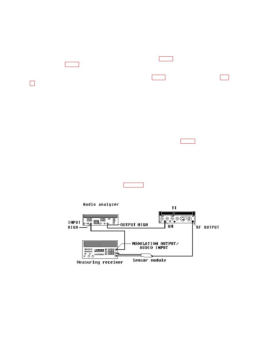
(1) Connect equipment as shown in figure 5.
